
Systems and methods for correcting banding defects using feedback and/or feedforward control

a technology of feedback and/or feedforward control, applied in the field of system and method for detecting and correcting image quality defects, can solve problems such as non-uniform photoreceptors, image quality defects introduced, banding defects, etc., and achieve the effect of reducing unit machine cost and being easy to scal

Inactive Publication Date: 2006-06-06
XEROX CORP
View PDF14 Cites 66 Cited by
  • Summary
  • Abstract
  • Description
  • Claims
  • Application Information

AI Technical Summary

Benefits of technology

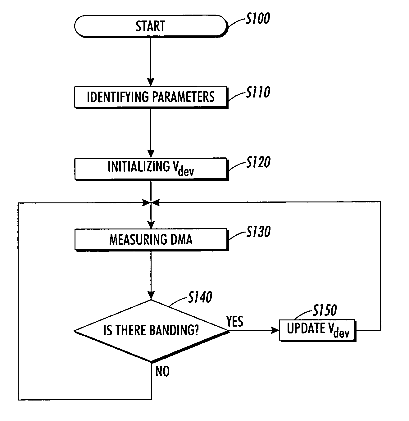
The patent text discusses the limitations of current methods for correcting banding defects in xerographic image marking devices. It proposes an "active" approach using feedback and feedforward control to mitigate these defects. The invention provides systems and methods for controlling image quality defects, such as banding, by detecting and correcting them using closed-loop feedback and feedforward control techniques. This approach allows for the use of components with relaxed tolerances, reducing unit machine cost, and easy scaling from one product to the next. Additionally, feedback and feedforward control is robust to subsystem variations.

Problems solved by technology

A common image quality defect introduced by the copying or printing process is banding.
Banding defects can result due to many xerographic subsystem defects such as, for example, development nip gap variation caused by developer roll runout and / or photoreceptor drum runout, coating variations on either the developer rolls or the photoreceptor, non-uniform photoreceptor wear and / or charging, and developer material variations.
One problem with this “passive” approach is that stringent image quality specifications increasingly lead to subsystem components with tighter and tighter tolerances, which, in turn, are more costly to manufacture.
Another potential problem is scalability.
That is, the subsystem design for one product in a family may not be appropriate for a different product in the same family, thus leading to costly and time consuming redesign.
Furthermore, specifying tight tolerances in subsystem design has limited robustness properties.
For example, using developer rolls with a tight tolerance on runout will not help with banding due to photoreceptor wear.

Method used


Image

  • Systems and methods for correcting banding defects using feedback and/or feedforward control
  • Systems and methods for correcting banding defects using feedback and/or feedforward control
  • Systems and methods for correcting banding defects using feedback and/or feedforward control

Examples


Embodiment Construction

[0028]These and other features and advantages of this invention are described in, or are apparent from, the following detailed description of various exemplary embodiments of the systems and methods according to this invention.

[0029]FIG. 3 schematically illustrates an exemplary image marking device developer housing 10, such as an electrophotographic (EP) device developer housing, and one or more optical sensors 50 that can be used to implement a feedback and / or feedforward loop control architecture for controlling banding defects in an image. As shown in FIG. 3, typical EP devices, such as photocopiers, scanners, laser printers and the like, may include a photoreceptor drum 20, which may be an organic photoconductive (OPC) drum 20, that rotates at a constant angular velocity. The EP device shown in FIG. 3 further includes a magnetic roll 30 and a trim bar 40.

[0030]As the OPC drum 20 rotates, it is electrostatically charged, and a latent image is exposed line by line onto the OPC dr...


PUM


Abstract

Systems and methods of controlling banding defects on a receiving member in an imaging or printing process using a feedback and / or feedforward control technique. In one exemplary embodiment, a method of controlling banding defects on a receiving member in an imaging or printing process includes (a) determining a toner density on the receiving member, (b) automatically determining the extent of banding on the receiving member by comparing the determined toner density to a reference toner density value, and (c) automatically adjusting the toner density based on a result obtained from the comparison of the measured toner density to the reference toner density value, automatically determining the extent of banding and automatically adjusting the toner density being performed using a feedback and / or feedforward control routine or application.

Description

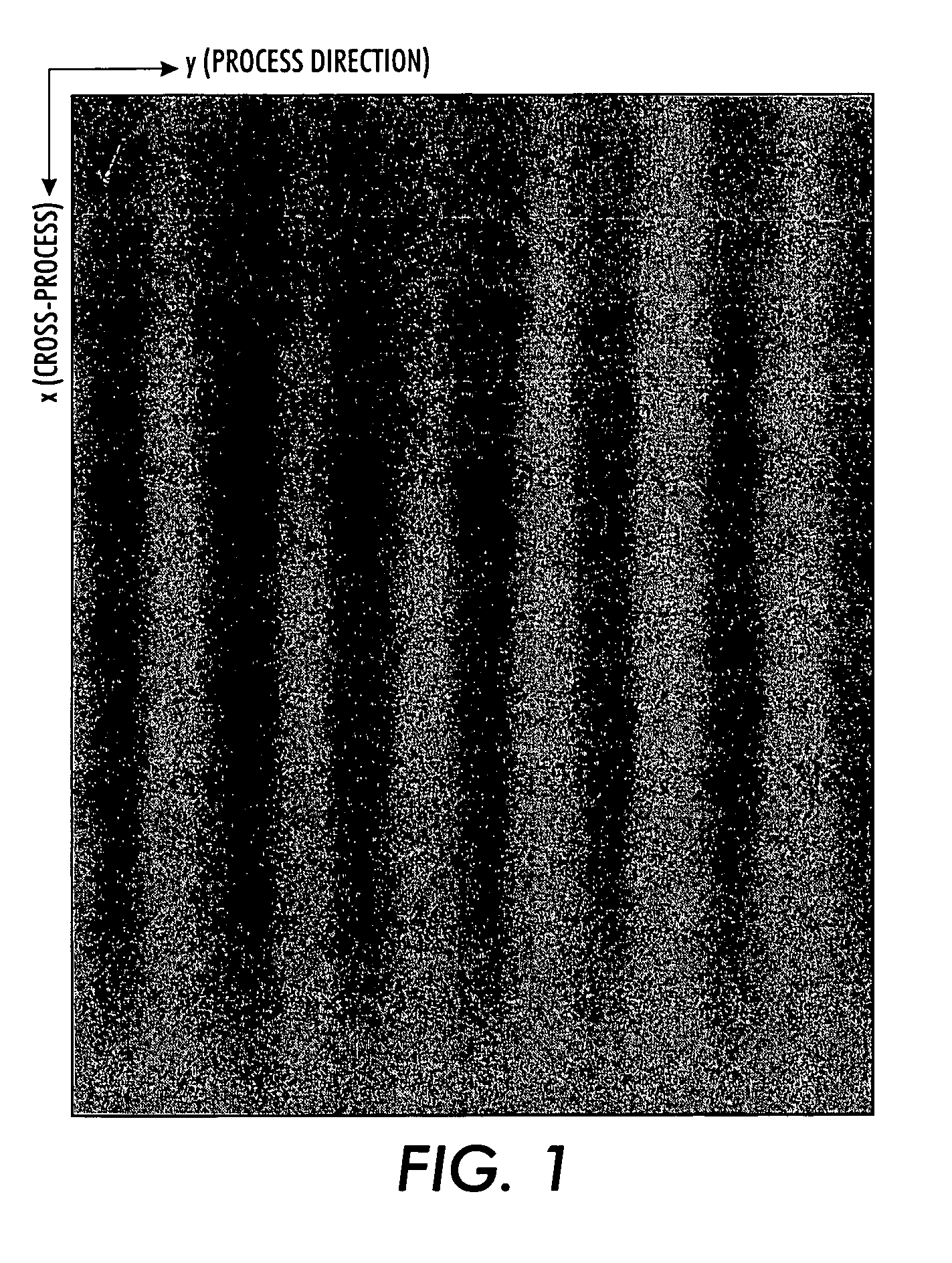
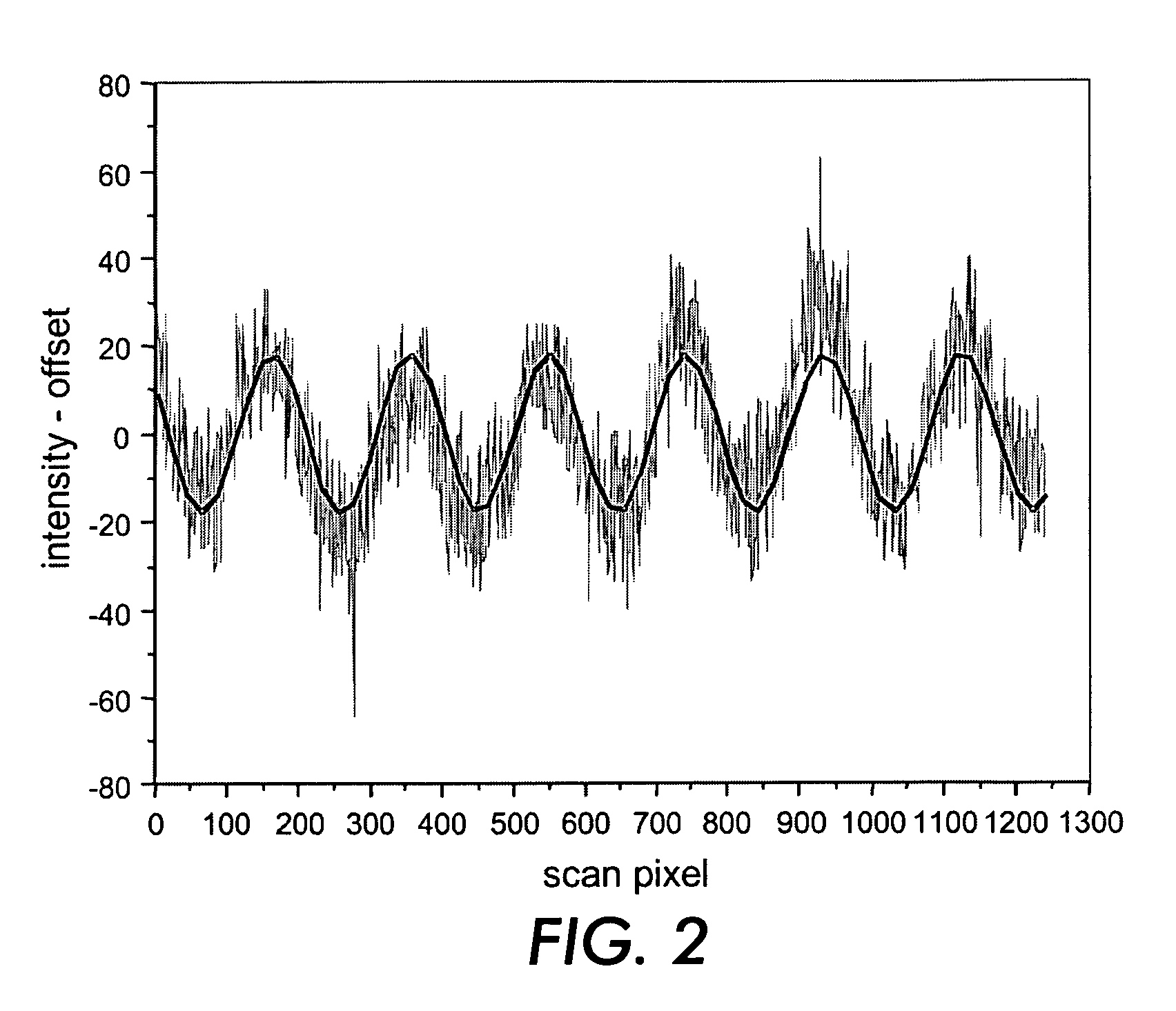
BACKGROUND OF THE INVENTION[0001]1. Field of Invention[0002]This invention relates to systems and methods for detecting and correcting image quality defects, such as banding defects, in image marking devices, such as, for example, xerographic marking devices, using feedback and / or feedforward control.[0003]2. Description of Related Art[0004]A common image quality defect introduced by the copying or printing process is banding. Banding generally refers to periodic, linear structures on an image caused by a one-dimensional density variation in either the cross-process (fast scan) direction or process (slow scan) direction. FIG. 1 shows an image taken from an image marking device, such as, for example, a xerographic printer that illustrates an extreme case of banding due to photoreceptor and magnetic roll runout. A typical density variation of this image in the process direction is shown in FIG. 2.[0005]Banding defects can result due to many xerographic subsystem defects such as, for e...

Claims


Application Information

Patent Timeline
Patent Type & Authority Patents(United States)
IPC IPC(8): G03G15/00G03G21/00H04N1/047
CPCG03G15/5062
Inventor HAMBY, ERIC S.GROSS, ERIC M.VIASSOLO, DANIEL E.THOMPSON, MICHAEL D.VITURRO, R. ENRIQUEXIAO, FEILANGE, CLARK V.
Owner XEROX CORP
Learn More