
X-ray apparatus capable of operating in a plurality of imaging modes

a technology of x-ray apparatus and imaging mode, which is applied in the field of x-ray apparatus, can solve the problems of insufficient definition of conventional cone beam ct apparatus, high cost of purchase of multiple flat-panel sensors, and high cost of flat-panel sensors

Inactive Publication Date: 2006-06-06
CANON KK
View PDF6 Cites 115 Cited by
  • Summary
  • Abstract
  • Description
  • Claims
  • Application Information

AI Technical Summary

Benefits of technology

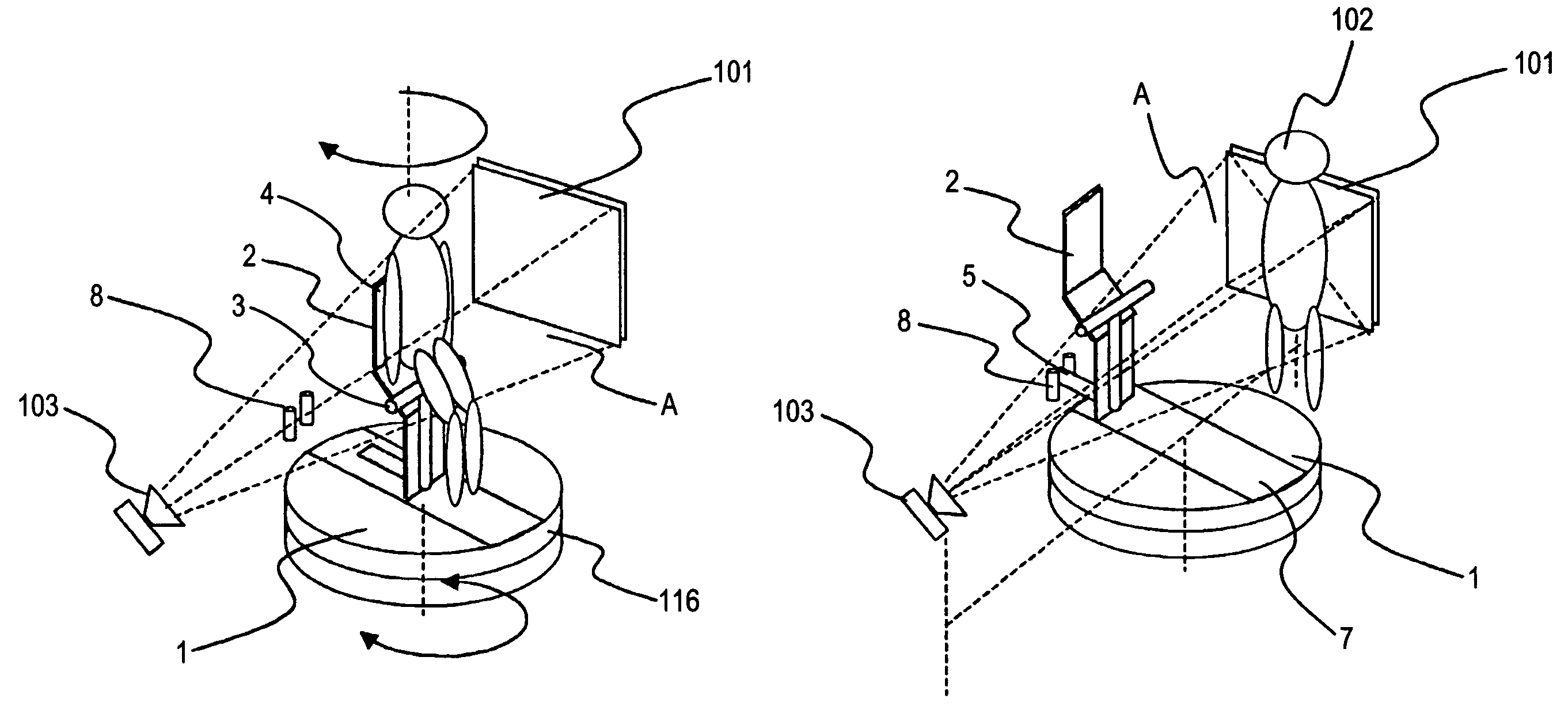
The present invention provides an X-ray apparatus that can rotate a subject and capture high-definition images in both the usual imaging mode and the CT imaging mode. The apparatus includes a rotatable table for rotating the subject, a securing member for securing the subject, a moving unit for moving the securing member between a position within the X-ray apparatus and a position outside the imaging field, a detecting unit for detecting the position of the securing member, and a controlling unit for inhibiting the apparatus from operating in the second imaging mode when the securing member is detected to be present within the imaging field. This ensures that the apparatus can operate in the desired imaging mode based on the position of the securing member.

Problems solved by technology

A flat-panel sensor is relatively expensive, so the purchase of multiple flat-panel sensors entails high cost.
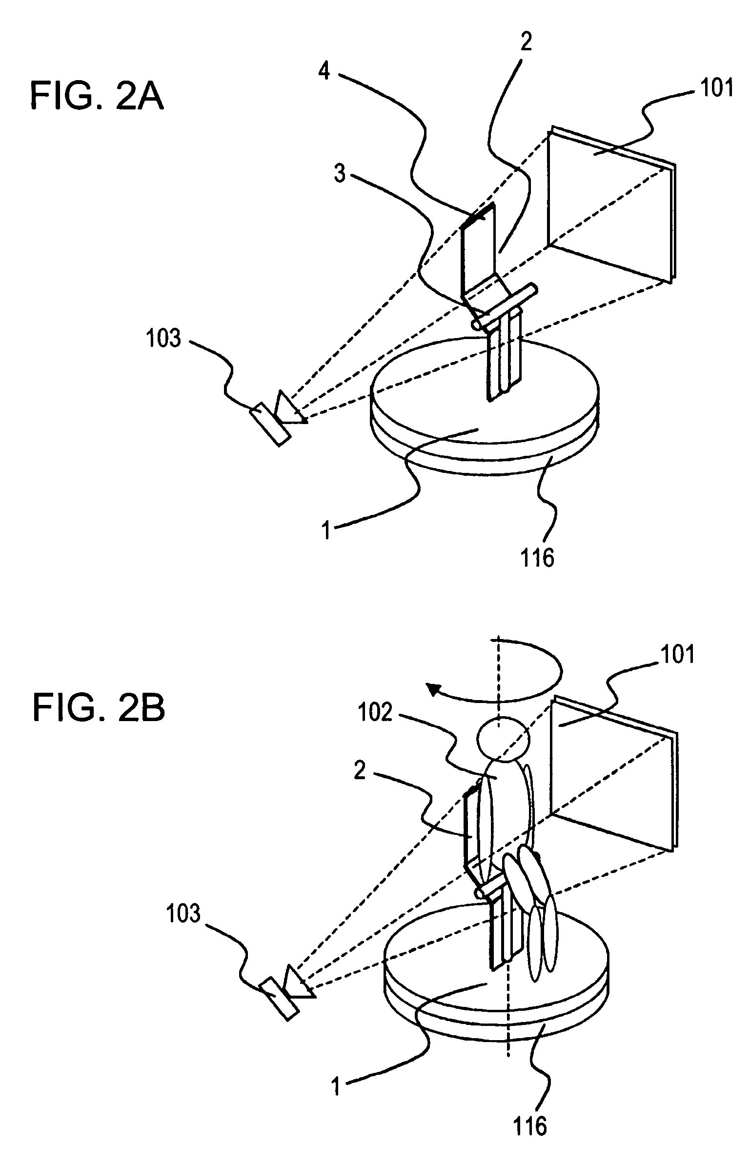
However, a conventional cone-beam CT apparatus cannot realize sufficient definition when performing the usual imaging because the chair 2, including a seat 3 and a backrest 4 and disposed on the rotatable table 1, is imaged in the resulting image.
On the other hand, when performing the cone-beam CT imaging on, for example, a knee, the chair 2 on the rotation axis will be an obstacle because the knee must be placed at the rotation center.

Method used


Image

  • X-ray apparatus capable of operating in a plurality of imaging modes
  • X-ray apparatus capable of operating in a plurality of imaging modes
  • X-ray apparatus capable of operating in a plurality of imaging modes

Examples


Embodiment Construction

[0019]The embodiments are described below with reference to the drawings.

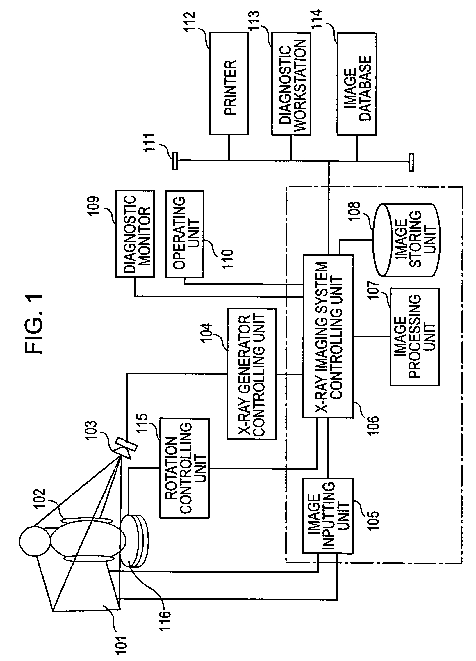
[0020]FIG. 1 is a block diagram schematically showing the entire structure of an X-ray apparatus according to an embodiment of the present invention.

[0021]An X-ray imaging system controlling unit 106 performs imaging control, image collection, image processing, and image outputting in the X-ray apparatus.

[0022]When the X-ray imaging system controlling unit 106 instructs an X-ray generator controlling unit 104 to generate X-rays, an X-ray source 103 controlled by the X-ray generator controlling unit 104 emits X-rays. The X-rays emitted from the X-ray source 103 pass through a subject 102 and are detected by an X-ray detector 101. The X-rays detected by the X-ray detector 101 are input as a projected image to an image inputting unit 105.

[0023]An operating unit 110 allows the imaging mode to be set. An operator of the X-ray apparatus selects the usual imaging mode or the CT imaging mode with the operating unit 110...


PUM


Abstract

An X-ray apparatus capable of performing both computerized tomography (CT) imaging and usual radiography imaging (usual imaging) can realize high definition even in the usual imaging. In the X-ray apparatus, for the usual imaging, since a chair serving as a supporting structure for supporting a subject on a rotatable table is not required, the chair is withdrawn from an imaging field. The usual imaging is controlled so as to be permitted when the supporting structure is withdrawn from the imaging field. For imaging a knee, for example, sliding the chair allows imaging keeping the knee being in the rotation center. Therefore, a wide variety of imaging operations can be realized with a single flat-panel sensor.

Description

BACKGROUND OF THE INVENTION[0001]1. Field of the Invention[0002]The present invention relates to an X-ray apparatus including a rotatable table for rotating a subject and being capable of operating in a first imaging mode of performing X-ray imaging while the subject is rotated and a second imaging mode of performing X-ray imaging while the subject remains stationary.[0003]2. Description of the Related Art[0004]A cone-beam X-ray computerized tomography (CT) apparatus is schematically shown in FIG. 2A. In this apparatus, a rotatable table 1 is disposed between an X-ray tube 103 and a flat-panel sensor 101. A chair 2 is fixed on the rotatable table 1.[0005]As shown in FIG. 2B, X-ray imaging is performed on a subject 102 sitting on the chair 2 while the rotatable table 1 is rotated. X-rays emitted from the X-ray tube 103 are absorbed and attenuated in the body of the subject 102. The transmitted X-rays are then detected by the flat-panel sensor 101. The subject 102 is rotated about its...

Claims


Application Information

Patent Timeline
Patent Type & Authority Patents(United States)
IPC IPC(8): A61B6/00H05G1/56G03B42/02
CPCA61B6/032A61B6/5235A61B6/0478A61B6/04
Inventor SAKO, TSUKASA
Owner CANON KK
Learn More