
Internal teeth oscillating inner gearing planetary gear system

a planetary gear system and inner gearing technology, applied in the direction of toothed gearings, belts/chains/gearings, gearings, etc., can solve the problems of large components, difficult to realize cost reduction, and difficult to form through holes in the central portion so as to improve the width dimension of the gear system, increase the amount of power transmission, and provide compact space

Inactive Publication Date: 2006-06-06
SUMITOMO HEAVY IND LTD
View PDF4 Cites 16 Cited by
  • Summary
  • Abstract
  • Description
  • Claims
  • Application Information

AI Technical Summary

Benefits of technology

[0016]The present invention was devised to solve these problems. It is an object to provide an internal teeth oscillating inner gearing planetary gear system in which layout space for piping, wiring, etc. can be easily maintained in the central portion of the system corresponding to particular applications, and in which further smoothness of power transmission can be achieved, while cost reduction by reducing the number of components, reduction of burden of stock, and other effects are made possible.
[0018]According to the present invention, internal oscillating bodies, which had been oscillatingly rotated by a plurality of eccentric shafts formerly, are oscillatingly rotated by one eccentric gear. Therefore, there is no need to dispose several sliding members such as rollers, transmitting gears, etc., which had to be disposed for each of several eccentric shafts. Thus, the cost is reduced through decreasing the number of components. Particularly, when several capacities, transmission ratios, etc. are to be provided as a group of gear systems, the entire number of stock components can be largely reduced. Moreover, an internal oscillating body can be driven by a single eccentric gear, so that the internal oscillating body can be oscillatingly rotated smoothly in a balanced manner. Thus a further smoothness of power transmission will be possible.
[0019]Further, since an eccentric gear is located radially outside the internal oscillating body, an input shaft for driving the eccentric gear does not have to be located in a central portion of a gear system. Accordingly, there is a greater degree of freedom in locating an input shaft. The space in the central portion of the gear system can also be used effectively.
[0021]Further, if a plurality of the internal oscillating bodies are provided in the axial direction for the same eccentric gear, the plurality of internal oscillating bodies can be simultaneously oscillatingly rotated by the single eccentric gear, and the amount of power transmission can be increased.
[0022]Moreover, if the input shaft is placed parallel to the axis of the eccentric gear, and the pinion of the input shaft is placed on an extension in the radial direction of the internal oscillating body, the width dimension of the gear system when viewing the input shaft from the side can be made smaller. Thus, the gear system can be designed smaller.
[0023]A construction may also be adopted wherein the input shaft is placed at a right angle to the axis of the eccentric gear, and an orthogonal gear mechanism is formed by the pinion of the input shaft and the gear of the eccentric gear. In this instance, a drive device for driving the gear system can be located in the radial direction of the gear system, to provide compactness of space.

Problems solved by technology

The number of components is therefore large, and as a result it is difficult to realize cost reduction.
Thus, for example, it is difficult to form a through-hole in the central portion of a gear system to pass wiring, piping, etc. therethrough.

Method used


Image

  • Internal teeth oscillating inner gearing planetary gear system
  • Internal teeth oscillating inner gearing planetary gear system
  • Internal teeth oscillating inner gearing planetary gear system

Examples


Embodiment Construction

[0028]With reference to the drawings, an embodiment of the present invention will be described.

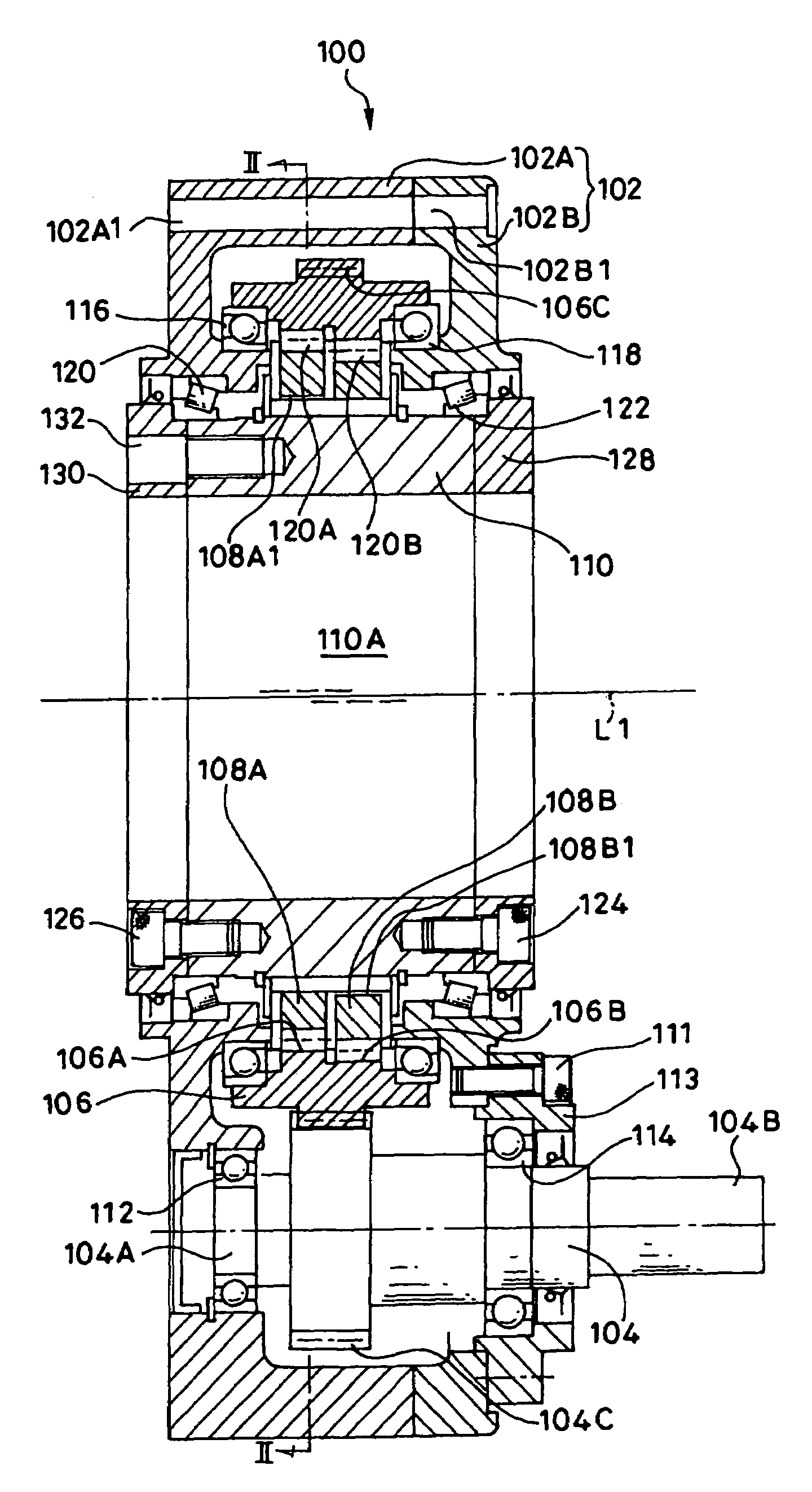
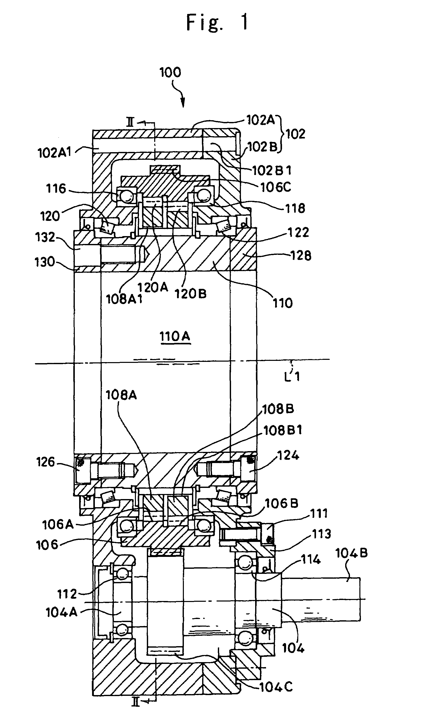
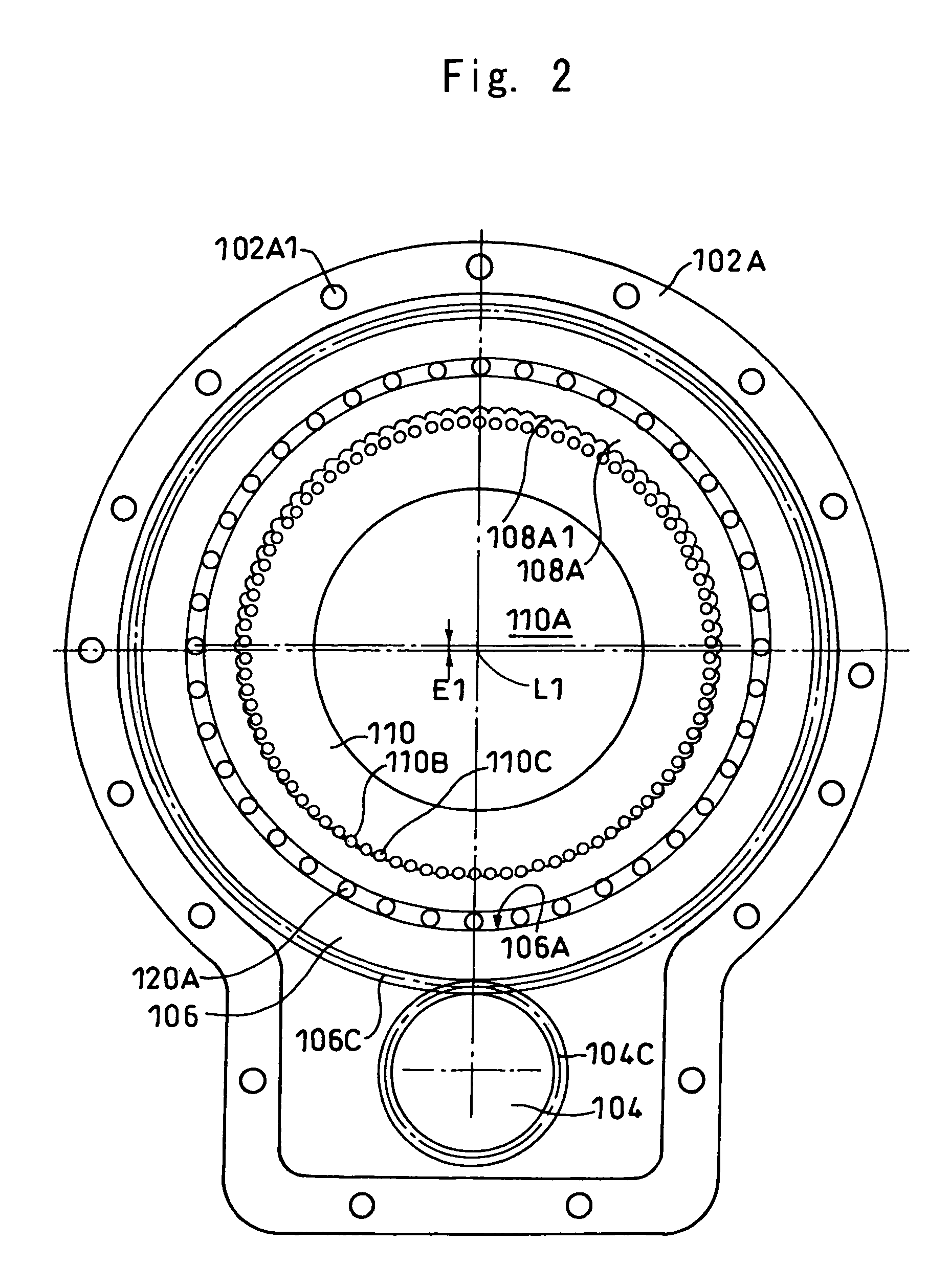
[0029]FIGS. 1 and 2 are drawings showing an internal teeth oscillating inner gearing planetary gear system 100 (hereafter, simply gear system) according to an embodiment of the present invention. FIG. 1 is a lateral cross-sectional view of the gear system 100, and FIG. 2 is a cross-sectional view taken along the line II—II in FIG. 1.

[0030]As shown in the drawings, the gear system 100 mainly comprises a main body casing 102, an input shaft 104, an eccentric gear 106, two internal oscillating bodies 108A and 108B, and an external gear 110 also serving a function as an output shaft.

[0031]The main body casing 102 comprises a first casing 102A and a second casing 102B located at the left and right respectively in FIG. 1. A plurality of bolt holes 102A1 and 102B1 are formed respectively in the first casing 102A and the second casing 102B so as to pass therethrough. The first casing 102A and the ...


PUM


Abstract

An internal teeth oscillating inner gearing planetary gear system is provided with an input shaft, an eccentric gear rotated by the input shaft, the internal oscillating body oscillatingly rotated through the inner circumferential surface of the eccentric gear, and an external gear meshed with the internal oscillating body.

Description

BACKGROUND OF THE INVENTION[0001]1. Field of the Invention[0002]The present invention relates to an internal teeth oscillating inner gearing planetary gear system.[0003]2. Description of the Related Art[0004]In the art, inner gearing planetary gear systems are employed widely in various reducer fields owing to the advantages of large torque transmission as well as the ability to achieve large reduction ratios.[0005]Among reducers, internal teeth oscillating inner gearing planetary gear systems are known wherein the rotation of an input shaft is reduced in speed and delivered from an output member by oscillatingly rotating internal oscillating bodies around an external gear, the internal oscillating body having a slight difference in the number of teeth with the external gear (for example, Japanese Patent No. 2607937).[0006]An example of the same gear system will be explained with reference to FIGS. 3 and 4.[0007]In the drawings, a casing 1 has a first support block 1A and a second s...

Claims


Application Information

Patent Timeline
Patent Type & Authority Patents(United States)
IPC IPC(8): F16H1/32
CPCF16H1/32
Inventor TSURUMI, YOHAGA, TAKASHI
Owner SUMITOMO HEAVY IND LTD
Learn More