Electrical connector box

a technology of electrical connectors and connector boxes, applied in the direction of coupling device details, coupling device connections, support structure mounting, etc., can solve the problem that the post member cannot be inserted into the pos

Inactive Publication Date: 2006-06-06
SUMITOMO WIRING SYST LTD
View PDF15 Cites 2 Cited by
  • Summary
  • Abstract
  • Description
  • Claims
  • Application Information

AI Technical Summary

Benefits of technology

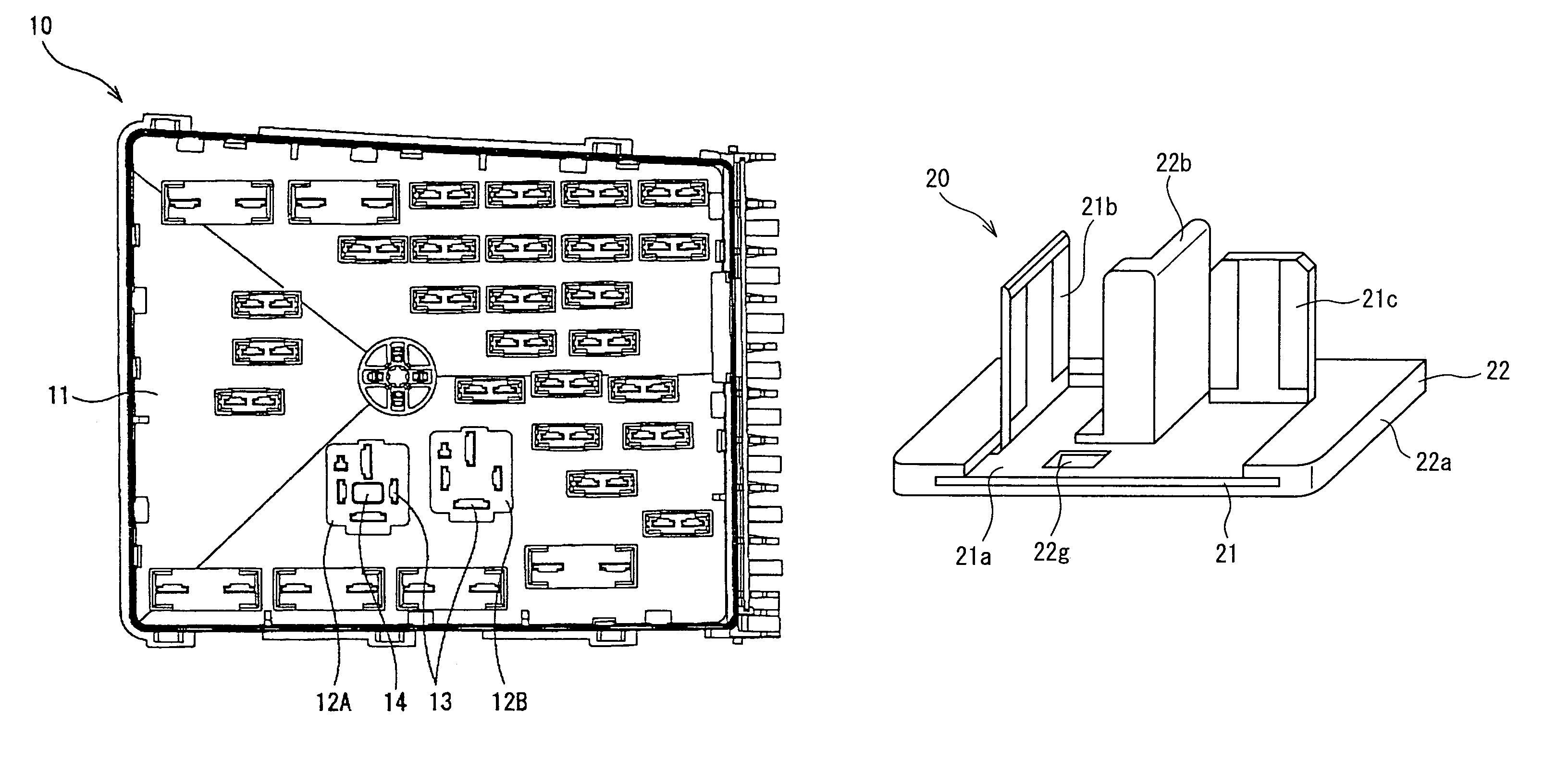
[0010]In a further aspect of the present invention, the shorting terminal includes a conductor plate including a link portion, the plurality of tabs projecting from the link portion; and a cover covering the link portion; wherein the post member extends from the cover in substantially the same direction as the tabs. Further, the post member may project beyond the tabs. The link portion may attach to the cover through a locking mechanism. Further, the post aperture is rectangular in shape and the post member is rectangular in cross section, such that the post member cannot be inserted into the post aperture if rotated 90 degrees. The post aperture may be L-shaped in cross section, such that the post member cannot be inserted into the post aperture if rotated 90 degrees.
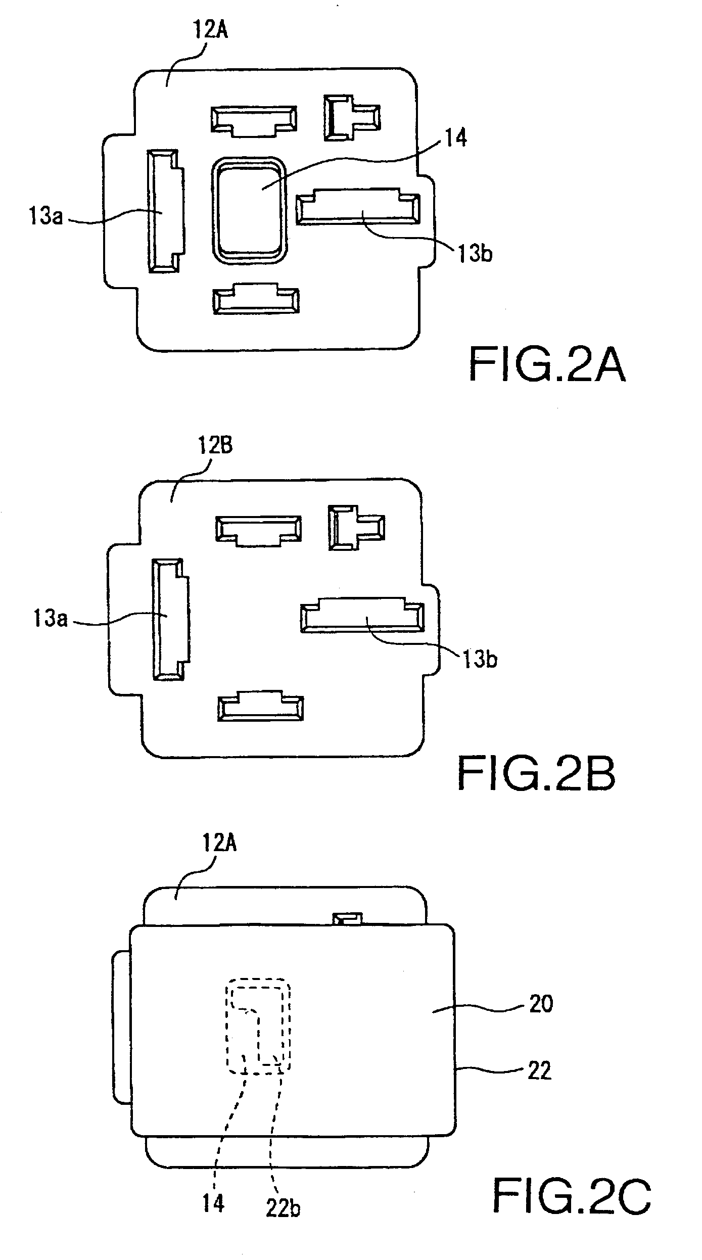
[0013]This structure of the present invention provides a shorting terminal on which a post member is formed extending in the same direction as the tabs, and a relay receptacle, on which a post aperture is formed, housing a contact circuit that may be shorted through the shorting terminal. Therefore, the attempted insertion of the tabs of the shorting terminal into the specified terminal slots in the relay receptacle results in the shorting terminal post part entering the post aperture in the relay receptacle, thus allowing the tabs to enter specified terminal slots. Conversely, when an attempt is made to insert the shorting terminal into a relay receptacle having an internal circuit not designed to be shorted, the post member contacts the face of the relay receptacle and prevents the tabs from entering the terminal slots. This structure allows the tabs of the shorting terminal to be inserted only into the specified terminal slots of a relay receptacle, and thus makes it possible to prevent the tabs from being mistakenly inserted into the wrong terminal slots of the relay receptacle. The structure of the present invention also makes it possible to prevent the tabs from being mistakenly inserted in an incorrect relay receptacle.
[0014]Further, the construction of present invention provides a cover to protect the shorting terminal. Furthermore, forming the post member from synthetic resin allows it to be fabricated to any desired size, shape, strength or other attribute.
[0015]It is preferable that the post part extend farther outward than the tabs. With this structure, an attempt to insert the shorting terminal into the wrong relay receptacle results in the post part contacting the face of the relay receptacle before the tabs can enter the terminal slots, thus preventing the tabs from coming into contact with the contact circuit in the case, and thus dependably preventing the formation of a short circuit. The present invention, in which the link portion of the shorting terminal attaches to the cover through a locking joint, or by being molded therein, allows simple fabrication of the shorting terminal. Moreover, the conductor plate of the shorting terminal may be used in the same manner as a conventional shorting terminal.
[0017]As previously noted, the invention provides for a shorting terminal from which a post part extends in the same direction as tabs, and a post hole formed within a relay receptacle within which a contact circuit is shorted through the shorting terminal. Therefore, the tabs enter the specified terminal slots when an attempt is made to insert the tabs of the shorting terminal into the specified terminal slots of a relay receptacle. Conversely, because a post hole is not provided in a relay receptacle having an internal circuit not intended to be shorted, an attempt to insert the tabs of the shorting terminal into the terminal slots of said relay receptacle results in the post part of the shorting terminal contacting the face of the relay receptacle, thereby preventing the tabs from entering the terminal slots. This structure allows the tabs of the shorting terminal to be inserted only into the specified terminal slots of a relay receptacle, and thus makes it possible to prevent the tabs from being mistakenly inserted into the wrong terminal slots of a relay receptacle.

Problems solved by technology

Further, the post aperture is rectangular in shape and the post member is rectangular in cross section, such that the post member cannot be inserted into the post aperture if rotated 90 degrees.

Method used


Image

  • Electrical connector box
  • Electrical connector box
  • Electrical connector box

Examples


Embodiment Construction

[0040]The particulars shown herein are by way of example and for purposes of illustrative discussion of the embodiments of the present invention only and are presented in the cause of providing what is believed to be the most useful and readily understood description of the principles and conceptual aspects of the present invention. In this regard, no attempt is made to show structural details of the present invention in more detail than is necessary for the fundamental understanding of the present invention, the description is taken with the drawings making apparent to those skilled in the art how the forms of the present invention may be embodied in practice.

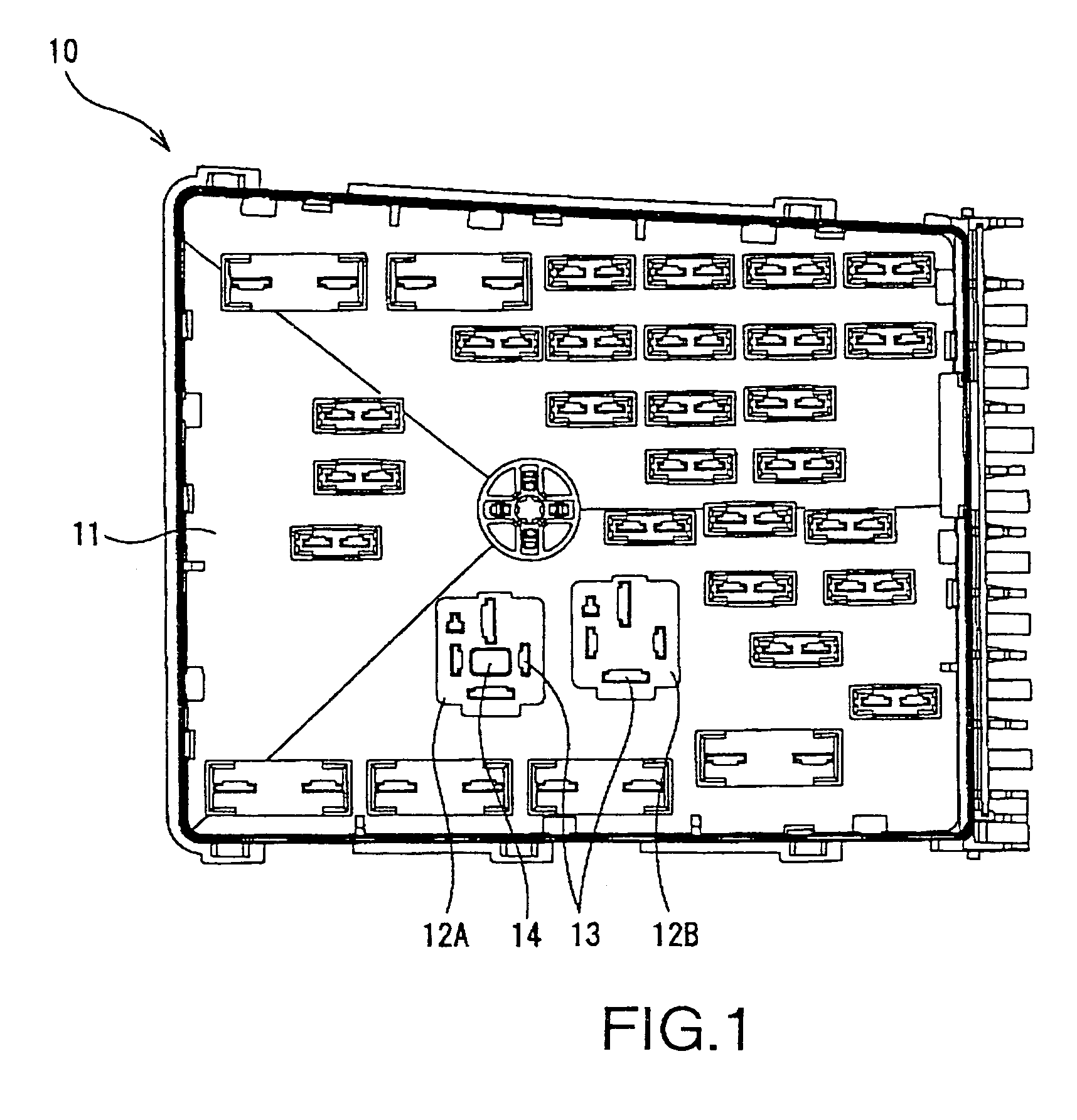
[0041]The following describes embodiments of the present invention with reference to the drawings. FIGS. 1 though 8 show an embodiment of the present invention including electrical connector box 10 to which two relay receptacles, 12A and 12B, are provided on the external surface of upper case 11.

[0042]As shown in FIG. 2A, rela...


PUM


Abstract

An electrical connector box constructed to prevent inaccurate insertion of a short circuit forming terminal to the contacts of an internal circuit. A shorting terminal includes a conductor plate having multiple tabs extending from a link portion, the link portion being covered by a cover, and a post that extends in the same direction as the tabs. A relay receptacle includes a post aperture into which post member of cover is inserted, thus allowing the tabs to enter specified terminal slots of the relay receptacle.

Description

CROSS REFERENCE TO RELATED APPLICATIONS[0001]The present disclosure relates to subject matter contained in priority Japanese Application No. 2004-098388, filed on Mar. 30, 2004, which is herein expressly incorporated by reference in its entirety.BACKGROUND OF THE INVENTION[0002]1. Field of the Invention[0003]The invention relates to an electrical connector box, and in particular to an electrical connector box constructed to prevent inaccurate insertion of a circuit shorting terminal into the terminal slots of a relay receptacle formed on the external surface of a case.[0004]2. Description of Related Art[0005]The internal circuits of an automotive electrical connector box are conventionally constructed in various configurations for use with various types of automobiles and various grades of automobiles within a model line. For example, when the internal circuit is formed from a bus bar that has been blank-formed to a required shape, the manufacture of each internal circuit requires t...

Claims


Application Information

Patent Timeline
Patent Type & Authority Patents(United States)
IPC IPC(8): H01R31/08H01R11/01H01R4/42H01R9/24H01R13/447H01R13/506H02G3/16H05K7/14
CPCH01R31/08H01R13/447H01R9/2458H01R13/506
Inventor SAKA, YUKINORIOKADA, KOUICHI
Owner SUMITOMO WIRING SYST LTD
Why Eureka
Try Eureka