Method and system for detecting network elements in an optical communications network

Active Publication Date: 2006-05-30
CIENA
View PDF15 Cites 41 Cited by
  • Summary
  • Abstract
  • Description
  • Claims
  • Application Information

AI Technical Summary

Problems solved by technology

For a typical long haul network, this can require a labor-intensive and time-consuming entry of hundreds of fiber optic port connections.
Due to the human factor, the process of manually provisioning network elements and updating the provisioning database is both time-consuming and prone to entry errors.
Often, the provisioning database does not accurately reflect physical network topology due to a failure to update physical changes in the provisioning database.

Method used


Image

  • Method and system for detecting network elements in an optical communications network
  • Method and system for detecting network elements in an optical communications network
  • Method and system for detecting network elements in an optical communications network

Examples


Embodiment Construction

[0023]The following detailed description of the invention refers to the accompanying drawings. The same reference numbers in different drawings identify the same or similar elements. Also, the following detailed description does not limit the invention. Instead, the scope of the invention is defined by the appended claims and equivalents thereof.

[0024]The expression “optically communicates” as used herein refers to any connection, coupling, link or the like by which optical signals carried by one optical system element are imparted to the “communicating” element. Such “optically communicating” devices are not necessarily directly connected to one another and may be separated by intermediate optical components or devices. Likewise, the expressions “connection” and “operative connection” as used herein are relative terms and do not require a direct physical connection.

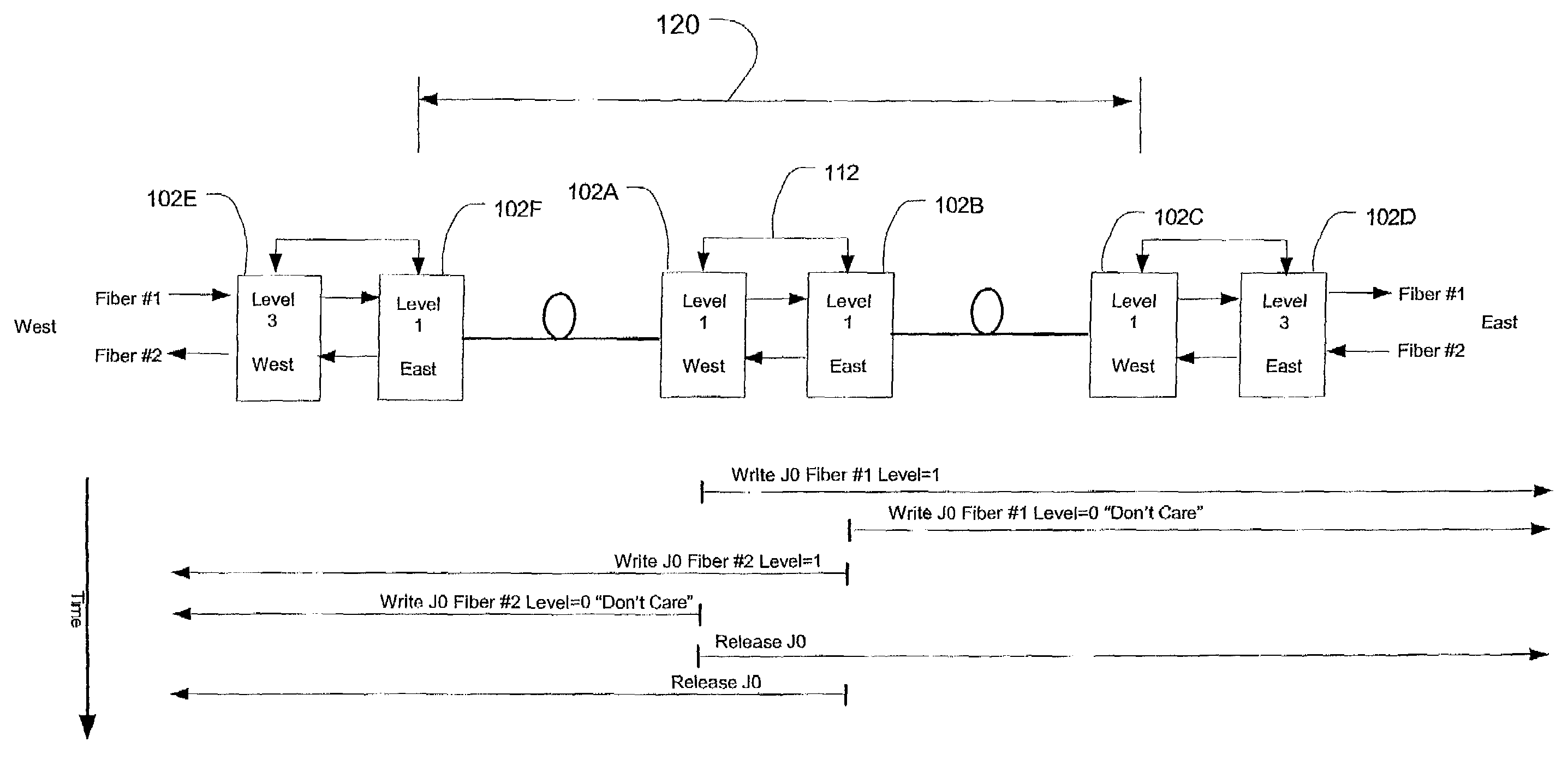
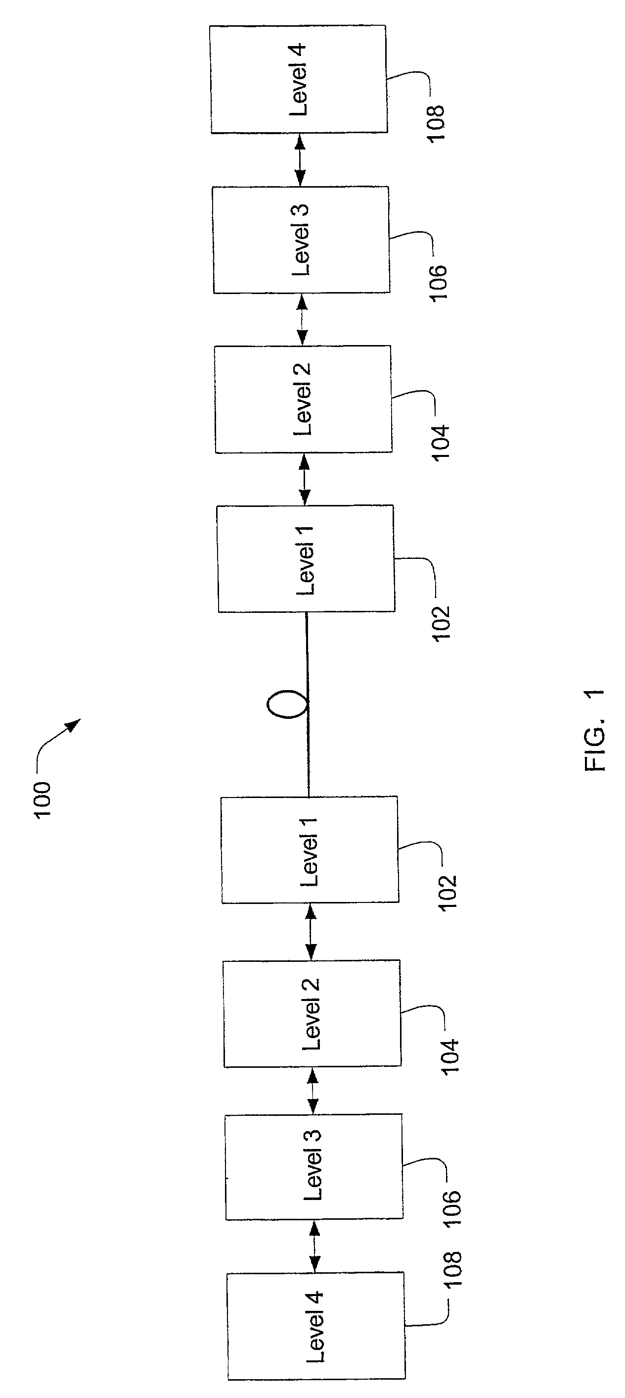
[0025]FIG. 1 is a block diagram of a portion of an exemplary optical communications network shown generally at 100. Th...


PUM


Abstract

An exemplary embodiment of the invention is a method of detecting network elements in an optical communications network. The method includes an initiating network element generating a neighbor discovery message including a requested hierarchy level at which neighbor discovery is requested and transmitting the neighbor discovery message downstream along the optical communications network. A downstream network element receives the neighbor discovery message, determines if the downstream network element operates at the requested hierarchy level. The downstream network element generates a responding neighbor discovery message if the downstream network element operates at the requested hierarchy level and transmits the responding neighbor discovery message to the initiating network element. Alternate embodiments include a system and storage medium for implementing the method.

Description

BACKGROUND OF THE INVENTION[0001]1. Field of Invention[0002]The invention relates generally to optical communications networks and in particular to a method and system for detecting network elements in an optical communications network.[0003]2. Description of Related Art[0004]In existing optical communications networks, network elements are provisioned to identify connections to ports on network elements. Existing networks rely on manual provisioning in which technicians perform initial provisioning and periodically update the provisioned information on a network element. The network topology may also be entered manually in a provisioning database. For a typical long haul network, this can require a labor-intensive and time-consuming entry of hundreds of fiber optic port connections. Due to the nature of a long haul network, the network elements may be physically distributed over a large geographic area. This necessitates sending technicians to these locations to verify the provisio...

Claims


Application Information

Patent Timeline
IPC IPC(8): H04B10/08H04B17/00H04L12/28H04L45/02H04Q11/00H04Q11/04
CPCH04L45/02H04Q11/0062H04L45/26H04J2203/0055H04Q2011/009H04Q2011/0088
Inventor MCNAMARA, ROBERTBERNSTEIN, GREG M.LEVIN, ROBERT A.HEBBAR, SRINIVASA
Owner CIENA
Why Eureka
Try Eureka