
Synchronous change of switchplane

a switch plane and switch plane technology, applied in data switching networks, frequency-division multiplexes, instruments, etc., can solve problems such as unwise handshaking techniques, complex redundant planes (which become active planes), and failure detection of active switch planes

Inactive Publication Date: 2006-05-30
TELEFON AB LM ERICSSON (PUBL)
View PDF18 Cites 4 Cited by
  • Summary
  • Abstract
  • Description
  • Claims
  • Application Information

AI Technical Summary

Benefits of technology

The patent describes a method for switching traffic in a network with multiple switch planes. When a fault is detected in an active switch plane, a passive switch plane is activated and traffic is redirected from the failed plane. The passive plane detects when traffic cells from the failed plane are flushed and becomes the active plane. This allows for smooth traffic flow and recovery from the fault. The method also includes using non-traffic cells to synchronize and manage the network. The technical effect of this patent is to improve the reliability and resilience of network switching.

Problems solved by technology

Detection of an failure of the active switch plane can be problematic.
Moreover, change over from the failed plane (which is to no longer serve as the active plane) to a redundant plane (which becomes the active plane) can be complex and liable to cell loss.
But such handshaking technique unwisely assumes that there is always a switch port interface unit connected to a particular egress port of the switch core.
Such assumption may not be correct, as the egress port of the core may be open for future use.
The timing considerations to protect against such a possibility introduce complex and awkward implementations of the handshaking procedures.

Method used


Image

  • Synchronous change of switchplane
  • Synchronous change of switchplane
  • Synchronous change of switchplane

Examples


Embodiment Construction

[0032]In the following description, for purposes of explanation and not limitation, specific details are set forth such as particular architectures, interfaces, techniques, etc. in order to provide a thorough understanding of the present invention. However, it will be apparent to those skilled in the art that the present invention may be practiced in other embodiments that depart from these specific details. In other instances, detailed descriptions of well known devices, circuits, and methods are omitted so as not to obscure the description of the present invention with unnecessary detail.

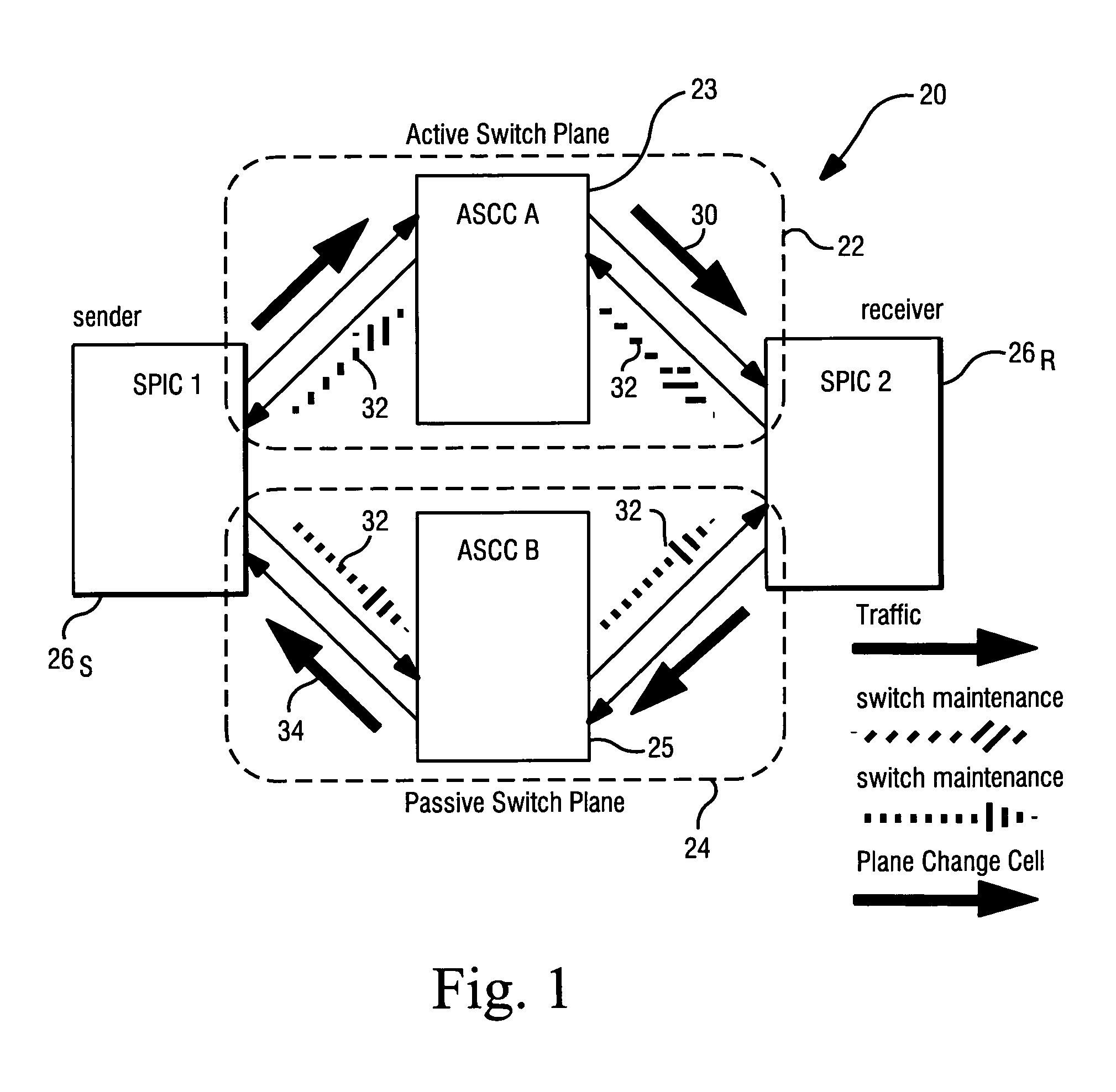
[0033]FIG. 1 illustrates an example switching node 20 of an embodiment of the invention. The switching node 20 comprise any type of cell switch, such as (for example), an ATM cell switch or an Internet Protocol (IP) router. The switching node 20 includes a first switch plane 22 (having a first plane switch core 23); second switch plane 24 (having a second plane switch core 25); sender switch port ...


PUM


Abstract

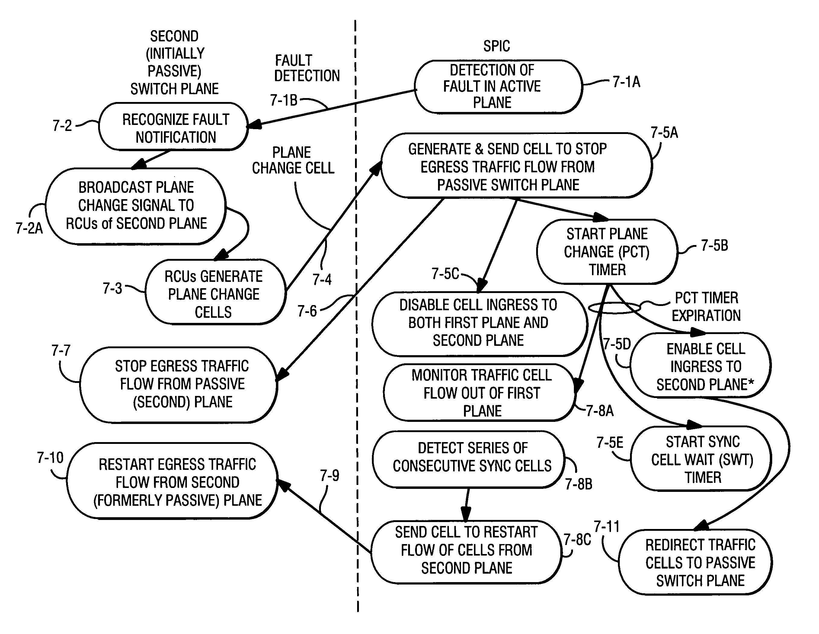
A change of switch plane operation is performed in a multi-plane cell switching node (20) which has a first switch plane (22); a second switch plane (24); and plural switch port interface units (26). In response to detection of a fault in the active switch plane, the passive switch plane sends a plane change cell to the plural switch port interface units, and stops egress traffic flow from the second switch plane. Upon receiving the plane change cell, each switch port interface unit redirects traffic cells sent from the active plane to the passive switch plane. Each switch port interface unit then determines when traffic cells destined thereto have been flushed from the first switch plane, and changes its active switch plane designation (so that the formerly passive switch plane becomes the active switch plane) so that egress traffic flow can begin from the formerly passive (now active) plane to the respective switch port interface units.

Description

[0001]This application is related to simultaneously filed U.S. patent application Ser. No. 09 / 688,165, entitled “FAULT DETECTION IN MULTI-PLANE SWITCH”, which is incorporated herein by reference in its entirety.BACKGROUND[0002]1. Field of the Invention[0003]The present invention pertains to cell switches, and particularly to cell switches which operate with plural switch planes.[0004]2. Related Art and Other Considerations[0005]Cell switches, such as ATM cell switches or Internet Protocol (IP) routers, are extensively employed in communication systems, such as mobile telecommunication systems, for example. Typically a communication node with a cell switch has a switch core which routes an incoming cell from an ingress port of the core to one or more egress ports of the core. The core ports are connected to respective switch port interface units (SPICs). In some systems, the switch port interface units reside on a board, with the board also having a board processor (BP) and (usually)...

Claims


Application Information

Patent Timeline
Patent Type & Authority Patents(United States)
IPC IPC(8): G01R31/08H04L12/56H04L49/116H04Q11/04
CPCH04L12/5601H04L49/153H04Q11/0478H04L49/203H04L2012/5627H04L2012/5646
Inventor LINDBLOM, MATSBERGHAGER, HANSSYDHOFF, PERKUNDEL, MIKAELBERGLUND, ASTRID
Owner TELEFON AB LM ERICSSON (PUBL)
Learn More