
Binary-coding pattern creating method and apparatus, binary-coding pattern, and computer-readable recording medium in which binary-coding pattern creating program is recorded

a technology creating method, which is applied in the field of binary coding pattern creating method and apparatus, and the creation of binary coding pattern, which can solve the problems of significant long time in creating binary coding pattern, inability to predict conversion, and significant frequency of errors and misidentifications, so as to achieve the desired pattern angle

Inactive Publication Date: 2006-05-23
FUJITSU LTD
View PDF7 Cites 1 Cited by
  • Summary
  • Abstract
  • Description
  • Claims
  • Application Information

AI Technical Summary

Benefits of technology

The present invention provides a method for creating a binary-coding pattern for a multi-value image that is easy to create and a minimum-sized binary-coding pattern. The method involves creating a basic pattern shape, determining the sequence of lighting pixels composing the basic pattern, and creating a rectangular pattern based on the basic pattern. The invention also provides an apparatus for carrying out the method and a computer-readable recording medium storing a binary-coding pattern creating program. The technical effects of the invention include ease of creating a binary-coding pattern and the ability to create a minimum-sized pattern.

Problems solved by technology

The above-described conventional binary-coding pattern creating methods, all of which depends on skilled operator's intuition and their experiences, have been accompanied with the following problems.
It is impossible to predict the conversion results that a prospective binary-coding pattern now being created would probably cause.
After much trial and error, it will be finally possible to select the most appropriate binary-coding pattern, thus necessitating a significantly long time in creating a binary-coding pattern.
Further, the binary-coding pattern thus selected is not always the best one, and also, errors and misidentifications occur significantly frequently because of manual operations performed by the operators.
Moreover, a try-and-error method would require increased resources (paper and ink, or else) because of repeated operations, thus being not economical.
Furthermore, in HEI 10-126618, the number of pixels assigned to each half tone dot is not always the same, because the number of cells varies in this method, so that unevenness might show up in output images, and moire might also appear on the boundaries of adjoining super cells.
In HEI 7-146945, since floating-point arithmetic operations are performed for obtaining the length of the sides of a super cell to be generated and the screen frequency of the super cell, a quantizing error finally obtained might be caused to be enormous.
Further, in HEI 10-75361, since two or more basic patterns are used to make up one single super cell for reducing errors, it is necessary to create a huge super cell, and the amount of memory needed for reading-in a halftone pattern would be significantly increased, thus causing increased hardware manufacturing costs.
In general, in case where the amount of coloring material (say, ink) to be fixed for each pixel on a print medium is very small, difficulties are encountered in fixing isolated spots of the material.
Accordingly, with recent printers realizing outputs of high resolution, the error-diffusing dithering has a problem of difficulty in fixing a tiny amount of coloring material for each pixel onto the print medium.

Method used


Image

  • Binary-coding pattern creating method and apparatus, binary-coding pattern, and computer-readable recording medium in which binary-coding pattern creating program is recorded
  • Binary-coding pattern creating method and apparatus, binary-coding pattern, and computer-readable recording medium in which binary-coding pattern creating program is recorded
  • Binary-coding pattern creating method and apparatus, binary-coding pattern, and computer-readable recording medium in which binary-coding pattern creating program is recorded

Examples


Embodiment Construction

)

[0098]One preferred embodiment of the present invention will now be described with reference to the accompanying drawings.

[0099](A) Description of One Embodiment

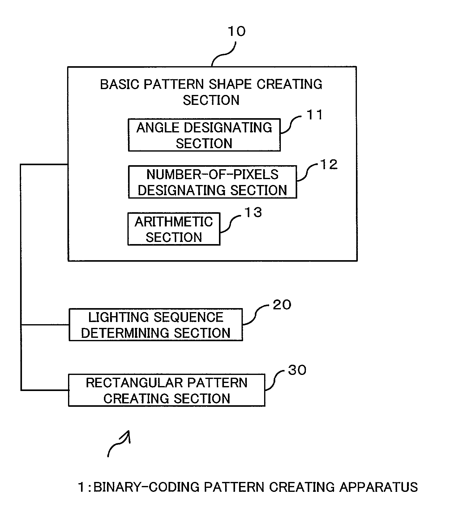
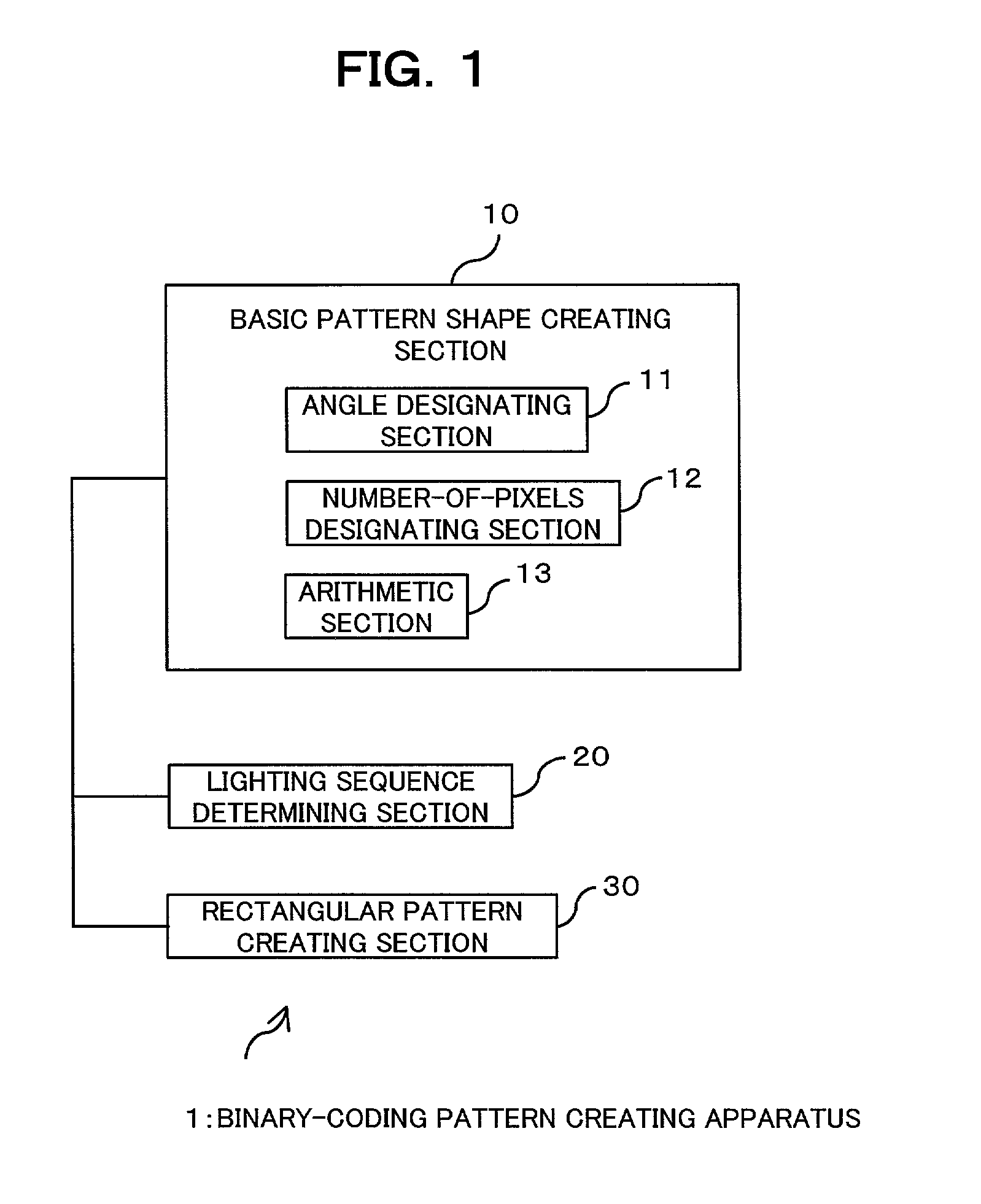
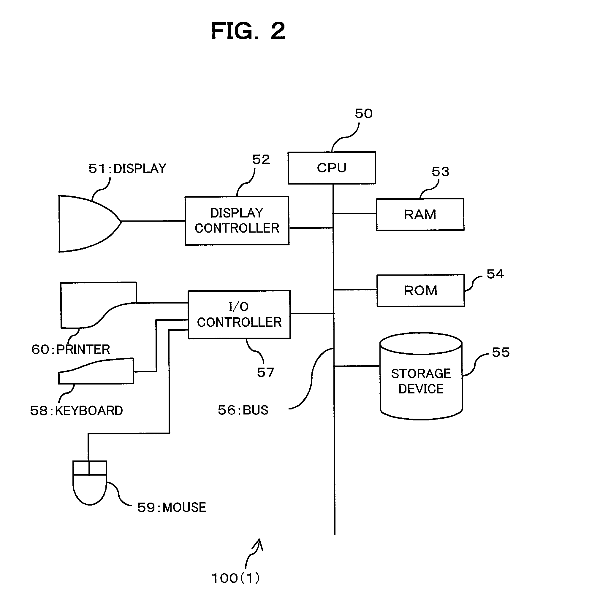
[0100]FIG. 1 and FIG. 2 show a binary-coding pattern creating apparatus which employs a binary-coding pattern creating method of one embodiment of the present invention: FIG. 1 is a function schematic; FIG. 2 is a hardware structure schematic. A binary-coding pattern creating apparatus 1 of the present embodiment creates a centralized type of binary-coding pattern that is used by printers or high-resolution printing devices for converting (binarizing / binary-coding) a multilevel image into a binary one.

[0101]For example, computer system 100 of FIG. 2 serves as binary-coding pattern creating apparatus 1 by means of executing a binary-coding pattern creating program stored in ROM 54 or storage device 55.

[0102]Computer system 100, as shown in FIG. 2, includes CPU 50, display 51, display controller 52, RAM 53, ROM 54, storage de...


PUM


Abstract

A method is provided for creating a binary-coding pattern to be used in binary-coding a multi-value image. The method includes the steps of: creating a basic pattern shape of the prospective binary-coding pattern by a first arithmetic operation; determining the sequence of lighting pixels composing such basic pattern by a second arithmetic operation; and creating a rectangular pattern, which serves as the prospective binary-coding pattern, based on the resultant basic pattern. Hereby, it is possible to automatically create a centralized type of binary-coding pattern, and also it is possible to facilitate creating a minimum-sized binary-coding pattern.

Description

BACKGROUND OF THE INVENTION[0001]1. Field of the Invention[0002]The present invention relates to a binary-coding pattern (dither pattern table) for use in converting continuous tone images (natural images, graphic images, colored characters, and others) into binary images—hereinafter this process will be also called “binary-coding”. The invention also relates to a method and an apparatus for creating such a binary-coding pattern and to a computer-readable recording medium in which a binary-coding pattern creating program is recorded.[0003]2. Description of the Related Art[0004]When continuous tone images (natural images, graphic images, and colored characters), which is input from input devices such as scanners, are output from output devices such as printers, the images must be converted into binary images, so that their continuous tone is expressed by ON / OFF of coloring materials (ink, toner, or the like; hereinafter also called “dot”).[0005]Dithering is a well-known method of suc...

Claims


Application Information

Patent Timeline
Patent Type & Authority Patents(United States)
IPC IPC(8): G06K9/36G06K9/18H04N1/40G06V30/224H04N1/405
CPCH04N1/4058
Inventor NAGAE, AKIKOUSUI, NOBUAKIASANO, TETSUO
Owner FUJITSU LTD
Learn More