
Geometric folding for cone-tree data compression

a data compression and geometries technology, applied in the field of computer graphics, can solve the problems of reducing the efficiency of graphics hardware systems, and requiring users to view more and more complex scenes at reasonable frame rates, so as to achieve the effect of increasing efficiency

Active Publication Date: 2006-05-23
ORACLE INT CORP
View PDF4 Cites 0 Cited by
  • Summary
  • Abstract
  • Description
  • Claims
  • Application Information

AI Technical Summary

Benefits of technology

"The patent describes a system and method for determining which objects are visible from a given viewpoint in a three-dimensional space. The system uses a combination of a cone tree and a hull tree to search for objects. The cone tree is based on a set of cones that are arranged in a hierarchy, with each cone having a set of visualization software that determines which objects it can see from a given viewpoint. The visualization software also uses a group of transformations to efficiently search the cone tree. The system can be implemented using a computer system and graphics display device. The technical effect of this patent is to provide a more efficient and effective way to determine which objects are visible from a given viewpoint in a three-dimensional space."

Problems solved by technology

In addition, visualization software has shown its cost effectiveness by allowing engineering companies to find design problems early in the design cycle, thus saving them significant amounts of money.
Unfortunately, the need to view more and more complex scenes has outpaced the ability of graphics hardware systems to display them at reasonable frame rates.
As scene complexity grows, visualization software designers need to carefully use the rendering resource provided by graphic hardware pipelines.
A hardware pipeline wastes rendering bandwidth when it discards rendered triangle work.
As scene complexity increases, especially in walk-through and CAD environments, the number of occluded surfaces rises rapidly and as a result the number of surfaces that the z-buffer discards rises as well.
As depth complexity rises, the hardware pipeline thus becomes proportionally less and less effective.
Computing a scene's visible objects is the complementary problem to that of occlusion culling.
In the discrete world of computer graphics, it is difficult to propagate a continuum of rays.
Of course, this implies that visible objects or segments of objects smaller than the resolution of the ray sample may be missed and not discovered.
The approach usually results in compact beams decomposing into a set of possibly non-connected cone(s) after interacting with an object.
The depth complexity of graphical environments continues to increase in response to consumer demand for realism and performance.
The computational bandwidth required by the visible object determination algorithm determines the class of processor required for the visualization system, and thereby affects overall system cost.
Furthermore, the large size of data structures associated with the visualization software may have a negative impact on performance and system cost.
A large data structure consumes memory space (especially RAM space) which could be used by other processes, takes a long time to transfer across physical interfaces, and implies a longer time to completion for the visibility algorithm.

Method used


Image

  • Geometric folding for cone-tree data compression
  • Geometric folding for cone-tree data compression
  • Geometric folding for cone-tree data compression

Examples


Embodiment Construction

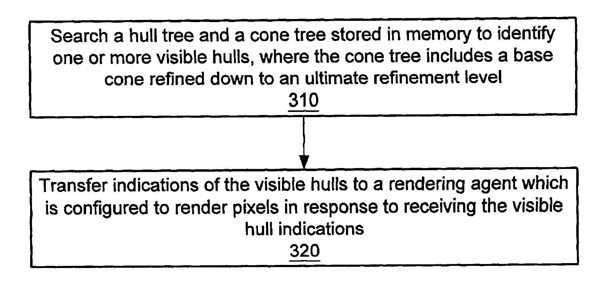
[0041]In one set of embodiments, a graphical computing system may be configured to operate on a collection of graphical objects so as to determine which of the objects are visible from a current viewpoint. The system searches a hierarchical tree of bounding hulls (or more general bounding structures) and a hierarchical tree of cones.

[0042]The tree of bounding hulls may be constructed from the bottom up, i.e. by generating first-order bounding hulls enclosing the graphical objects, second order bounding hulls enclosing groups of the first order bounding hulls, and so on, until at some level there is a single bounding hull enclosing the whole collection of objects.

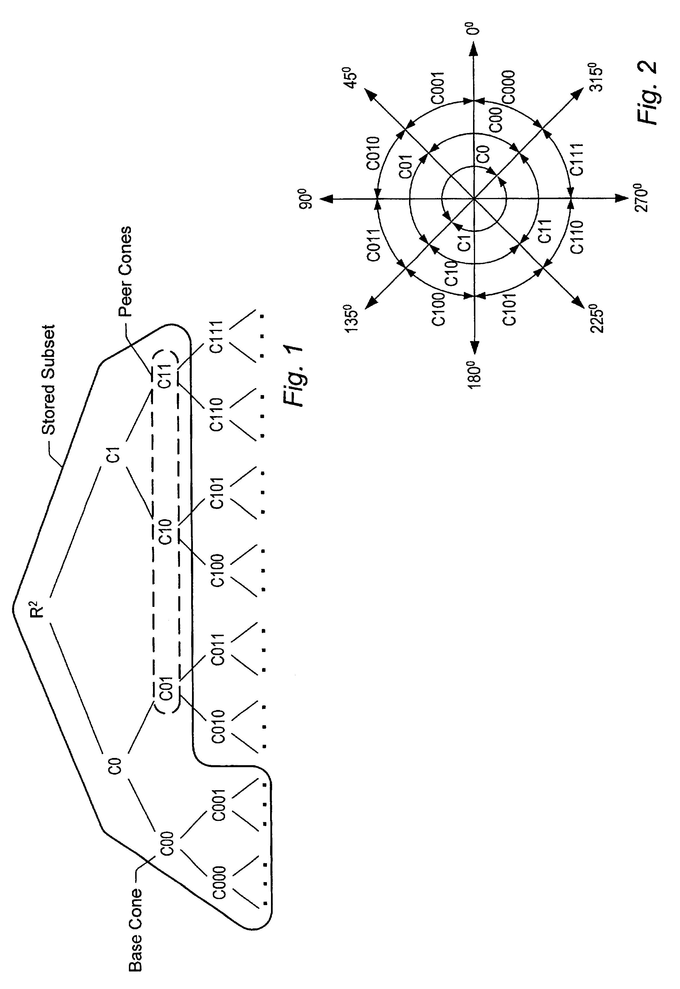
[0043]The tree of cones may be constructed from the top down. A three dimensional space may be interpreted as a cone (i.e. as the union of all rays emanating from the origin). The 3D space may be partioned into some number of first order subcones. The first order subcones may be partitioned into second order subcones, and so...


PUM


Abstract

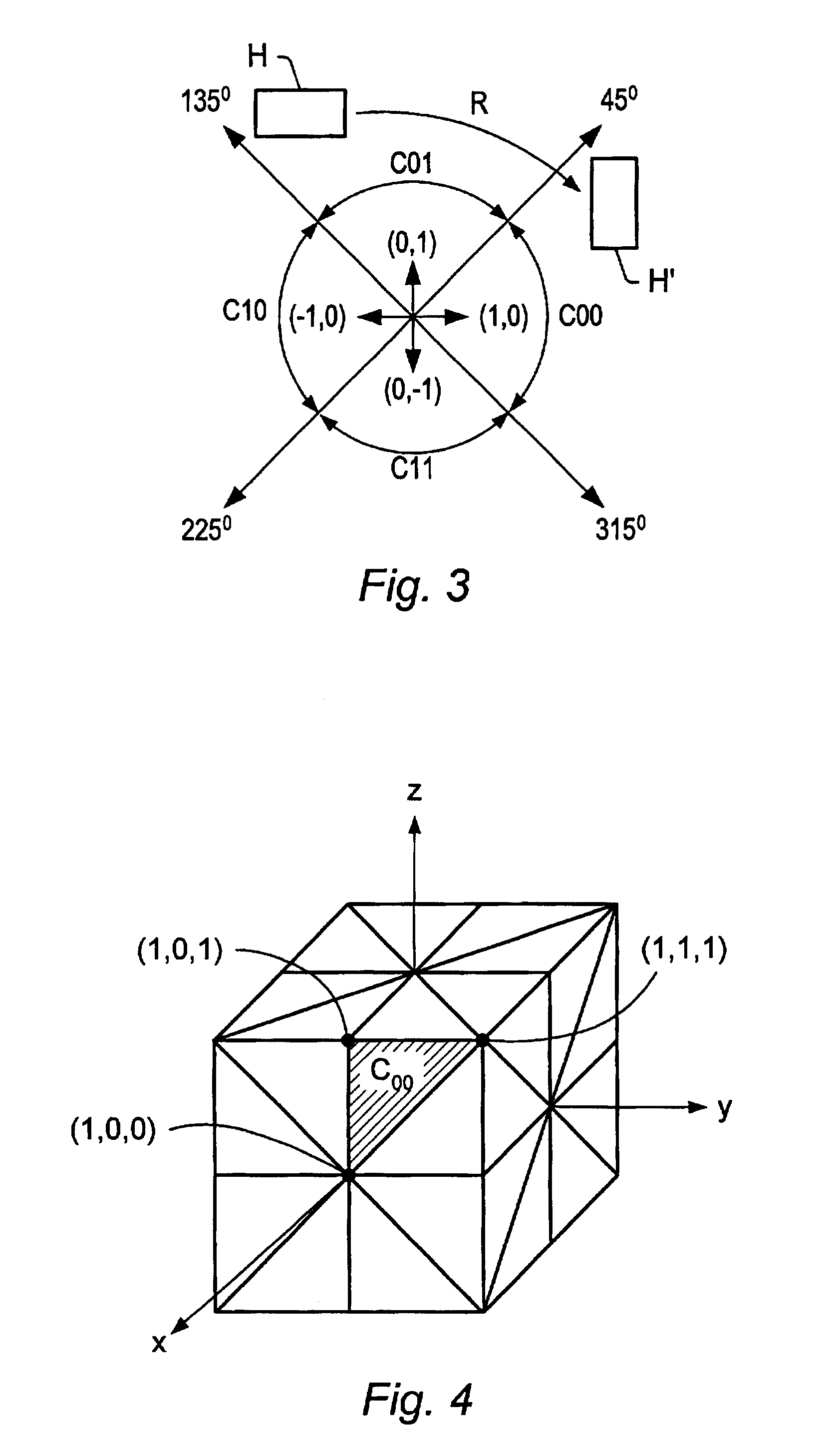
A system for performing visible object determination. Visualization software executing on one or more processors searches a cone tree with respect to a hull tree. Both trees respect the same group of transformations. Thus, the cone tree as stored in memory need not store all branches down to ultimate resolution. For example, the cone tree may store a selected cone and all its subcones down to the ultimate resolution, while subcones of other cones at the same level as the selected cone may not be represented in the stored cone tree. When the visualization software encounters a nonstored cone and a given hull H in its search procedure, the visualization software may apply an appropriate one of the group transformations to the given hull, and search the tranformed hull with respect to the selected cone (or a subcone of the selected cone).

Description

BACKGROUND OF THE INVENTION[0001]1. Field of the Invention[0002]The present invention relates generally to the field of computer graphics, and more particularly, to the problem of determining the set of objects (and portions of objects) visible from a defined viewpoint in a graphics environment.[0003]2. Description of the Related Art[0004]Visualization software has proven to be very useful in evaluating three-dimensional designs long before the physical realization of those designs. In addition, visualization software has shown its cost effectiveness by allowing engineering companies to find design problems early in the design cycle, thus saving them significant amounts of money. Unfortunately, the need to view more and more complex scenes has outpaced the ability of graphics hardware systems to display them at reasonable frame rates. As scene complexity grows, visualization software designers need to carefully use the rendering resource provided by graphic hardware pipelines.[0005]...

Claims


Application Information

Patent Timeline
Patent Type & Authority Patents(United States)
IPC IPC(8): G06T15/40G06T9/00G06T15/00G09G5/00
CPCG06T9/001
Inventor SOWIZRAL, HENRY A.ZIKAN, KARELKELLER, RANDALL G.
Owner ORACLE INT CORP
Learn More