
Reel clutch of a tape recorder

a tape recorder and reel clutch technology, applied in the direction of printers, mechanical tension control of carriers, instruments, etc., can solve the problems of high price of the magnet employed in the conventional magnetic recording/recording apparatus, the overall construction becomes complicated, and the difficulty in achieving the effect of simple construction

Inactive Publication Date: 2006-05-23
SAMSUNG ELECTRONICS CO LTD
View PDF15 Cites 5 Cited by
  • Summary
  • Abstract
  • Description
  • Claims
  • Application Information

AI Technical Summary

Benefits of technology

[0014]Accordingly, it is an aspect of an embodiment of the present invention to provide a reel assembly driving apparatus and a reel assembly of a magnetic recording / reproducing apparatus, which is improved to have a simple construction.

Problems solved by technology

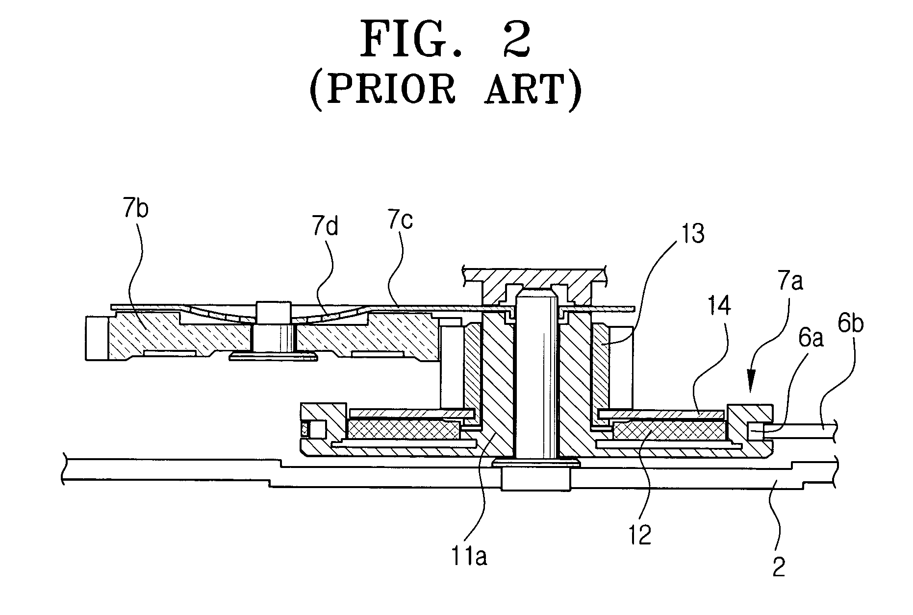
However, in the conventional magnetic recording / reproducing apparatus constructed as above, because some components are required to provide a predetermined frictional force to the idle gear 7b to pivot the pivoting plate 7c, the overall construction becomes complicated.
Further, as additional components are also required to control the torque to the tape cassette reel, the construction of the magnetic recording / reproducing apparatus becomes still more complicated.
Also, because the price of the magnet employed in the conventional magnetic recording / reproducing apparatus is usually high, the manufacturing costs increase.
However, the problem is that this substitute also requires expensive components of rather complicated structure.

Method used


Image

  • Reel clutch of a tape recorder
  • Reel clutch of a tape recorder
  • Reel clutch of a tape recorder

Examples


Embodiment Construction

[0028]A reel assembly and a reel assembly driving apparatus of the magnetic recording / reproducing apparatus according to an embodiment of the present invention will now be described in greater detail with reference to the accompanying drawings and the preferred embodiments of the present invention.

[0029]Referring to FIGS. 3 and 4, the reel assembly of the magnetic recording / reproducing apparatus according to one preferred embodiment of the present invention includes a lower reel 31 rotatable with respect to a stationed axis 2a at the main deck 2, an upper reel 33 (or reel disc) joined with the upper portion of the lower reel 31 (or stopper reel), and a clutch member 37 disposed between the lower and upper reels 31, 33.

[0030]The lower reel 31 has an axis portion 31b protruding from the center of a circular body 31a to a predetermined height. The stationed axis 2a is fit with respect to the axis portion 31b. Around the lower portion of the axis portion 31b and on the upper surface of ...


PUM

PropertyMeasurementUnit
torqueaaaaaaaaaa
tensionaaaaaaaaaa
frictionaaaaaaaaaa

Abstract

Disclosed is a reel clutch of a tape recorder. A plate spring is positioned between a reel gear and a reel disc of a reel disc assembly which is mounted on a deck of a tape recorder, and a stopper reel is provided on the reel disc to restrain the engaging height of the plate spring so that a torque is generated by the frictional contact between the reel disc and the plate spring, whereby assembly productivity can be enhanced and manufacturing costs can be reduced.

Description

FOREIGN PRIORITY INFORMATION[0001]This application claims priority under 35 U.S.C. § 119 to a Korean Patent Application, Serial No. 2002-61821, filed in the Korean Intellectual Property Office on Oct. 10, 2002, to Korean Patent Application Serial No. 2002-68836, filed in the Korean Intellectual Property Office on Nov. 7, 2002, to Korean Patent Application Serial No. 2002-71728, filed in the Korean Intellectual Property Office on Nov. 18, 2002, and to Korean Patent Application Serial No. 2003-3426, filed in the Korean Intellectual Property Office on Jan. 17, 2003, the contents of all four said applications being incorporated herein by referenceBACKGROUND OF THE INVENTION[0002]1. Field of the Invention[0003]The present invention relates to a magnetic recording / reproducing apparatus, and more particularly, to a reel apparatus for driving a tape cassette of a magnetic recording / reproducing apparatus.[0004]2. Description of the Related Art[0005]Generally, a magnetic recording / reproducing...

Claims


Application Information

Patent Timeline
Patent Type & Authority Patents(United States)
IPC IPC(8): G11B15/44G11B15/08G11B15/32G11B15/30G11B15/43
CPCG11B15/43
Inventor KIM, BONG-JOOCHOI, HYEONG-SEOKSEO, JAE-KABKIM, JUN-YOUNGPARK, BYEONG-BAE
Owner SAMSUNG ELECTRONICS CO LTD
Learn More