Kitchen exhaust optimal temperature span system and method

a technology of optimal temperature span and exhaust system, which is applied in ventilation systems, heating types, stoves or ranges, etc., can solve problems such as conflicting determinations, single formula or single curves that do not always provide optimal exhausting conditions, and rely on fixed results

Active Publication Date: 2006-05-23
MELINK CORP
View PDF7 Cites 71 Cited by
  • Summary
  • Abstract
  • Description
  • Claims
  • Application Information

AI Technical Summary

Benefits of technology

[0007]In those systems where the fan speed was varied in relation to exhaust temperature, for example, the relationship between that temperature and the fan speed could be seen as a fixed mathematical formula or as a single curve on a graph. I have discovered, however, that reliance on a fixed, single formula or single curve does not always provide optimal exhausting conditions. To this end, and in accordance with principles of the present invention, I have discovered that varying the formula or the curve (or by selecting from various formulae or curves) which defines the relationship by which fan speed is varied relative to exhaust temperature, can produce more optimal exhausting conditions within the facility. Advantageously, the relationship is varied in response to environmental parameters of the kitchen and / or ambient environment.

Problems solved by technology

I have discovered, however, that reliance on a fixed, single formula or single curve does not always provide optimal exhausting conditions.
I have discovered that there are various conditions in which the typical temperature span is not sufficient to provide the most desirable results.
With a number of different parameters available to effect the operating temperature span, different analyses based on these parameters may result in conflicting determinations about how to best change the operating temperature span.

Method used


Image

  • Kitchen exhaust optimal temperature span system and method
  • Kitchen exhaust optimal temperature span system and method
  • Kitchen exhaust optimal temperature span system and method

Examples


Embodiment Construction

Exemplary Exhaust System and Environment

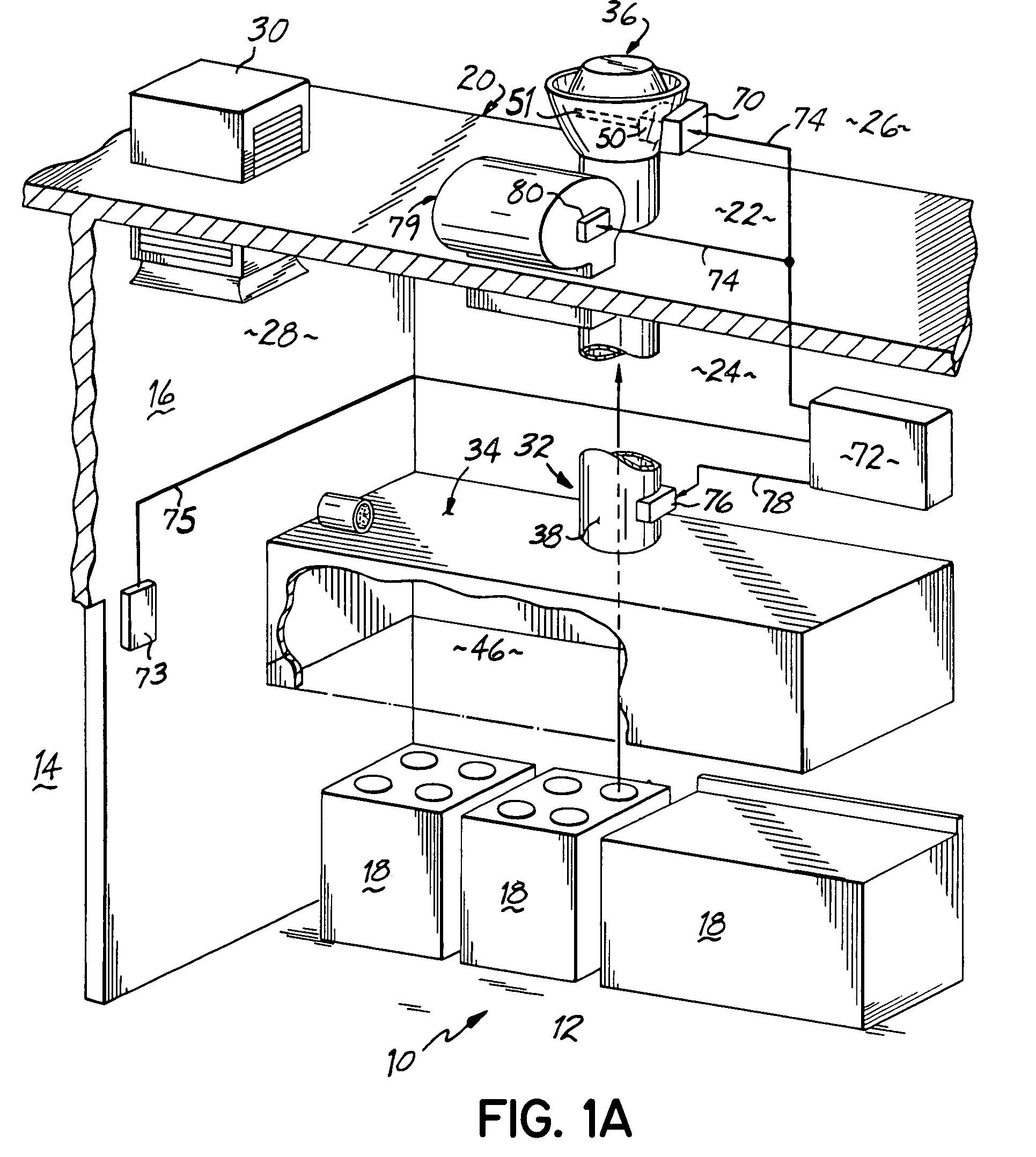
[0028]Referring to FIG. 1A, a facility 10 such as a restaurant or institutional facility includes a kitchen 12 and at least one adjacent room such as a dining room 14 with an interior wall 16 separating the two rooms 12, 14. Kitchen 12 includes a plurality of commercial cooking units 18 such as one or more stoves, ovens, griddles and the like. The facility 10 is typically surrounded by an enclosure 20 (defined by a roof 22 and exterior walls 24 only one of which is shown in FIG. 1A) which separates the outside environment 26 from the inside ambient air environment 28 of facility 10 including kitchen 12. Facility 10 is also equipped with a heating, ventilating and air conditioning system (“HVAC”) as at 30 which maintains the inside environment 28 at a suitable condition for the use of the occupants of facility 10.

[0029]Associated with kitchen 12 is kitchen exhaust system 32 including an exhaust hood 34 situated over the cooking units 18 and com...


PUM


Abstract

An exhaust control system (72) for a commercial or institutional kitchen exhaust system (32) is disclosed in which the exhaust fan speed is optimized for the amount of cooking heat and cooking by-product generated by the cooking units, as well as for comfort in the kitchen (12). Kitchen comfort is determined by sensing temperature, humidity, noxious gases, smoke, odor, or some combination thereof. In particular, exhaust air temperature can be used by the control system (72) to modulate fan speed from a minimum value to a maximum value based on the minimum and maximum temperatures that define a particular temperature span. During operation, the control system (72) continues to monitor environmental parameters of the kitchen (12) to determine if the current temperature span provides optimal performance. Upon determining that the current temperature span is no longer the optimal one, the control system (72) operates the exhaust system (32) according to a different temperature span.

Description

BACKGROUND OF THE INVENTION[0001]I. Field of the Invention[0002]The present invention relates to commercial and institutional kitchen exhaust systems, and more particularly, to an exhaust rate control method and apparatus for such exhaust systems.[0003]II. Discussion of Prior Art[0004]Commercial and institutional kitchens are equipped to prepare food for large numbers of people and may form part of or adjoin larger facilities such as restaurants, hospitals and the like. Such kitchens are typically equipped with one or more commercial duty cooking units capable of cooking large amounts of food. On such a scale, the cooking process may generate substantial amounts of cooking heat and airborne cooking by-products such as water vapor, grease particulates, smoke and aerosols, all of which must be exhausted from the kitchen so as not to foul the environment of the facility. To this end, large exhaust hoods are usually provided over the cooking units, with duct work connecting the hood to ...

Claims


Application Information

Patent Timeline
Patent Type & Authority Patents(United States)
IPC IPC(8): F24F7/00B08B15/02F24C15/20F24F7/06
CPCF24C15/2021F24F7/06F24F11/0012Y02B30/78F24F11/0017F24F2007/001F24F11/0015F24F11/30F24F2110/10F24F2110/20F24F2110/50Y02B30/70F24F11/77F24F11/526F24F11/76F24F11/46F24F11/64F24F11/33
Inventor MELINK, STEPHEN K.
Owner MELINK CORP
Why Eureka
Try Eureka