
Method for displaying controls in a system using a graphical user interface

a graphical user interface and control technology, applied in the field of display and manipulation of command related items in a graphical operating system, can solve the problems of large number of commands that require displaying a large number of controls, may not be operated using a keyboard, and conventional toolbars require the use of a pointing device, so as to reduce the use of different customization procedures, reduce the use of pointing devices, and improve the efficiency of use and screen spa

Inactive Publication Date: 2006-05-16
MICROSOFT CORP
View PDF5 Cites 19 Cited by
  • Summary
  • Abstract
  • Description
  • Claims
  • Application Information

AI Technical Summary

Benefits of technology

[0013]Therefore, there is a need in the art for an improved command bar that overcomes these drawbacks. An improved command bar would allow all controls to be included in either menu-type containers or toolbar-type containers and would include visual cues that indicate the linkage between similar commands. In addition, an improved command bar would allow the user to have greater control over what commands can be put where, thereby allowing commonly used controls to be placed in a toolbar-type container and less commonly used controls to be placed in a menu-type container. This would allow rich, interactive controls to be placed in a menu popup, and would increase efficiency of use and of screen space. An improved command bar would eliminate the use of different cust

Problems solved by technology

A corresponding disadvantage of toolbars is that exposing a large number of commands requires displaying a large number of controls, which require a relatively large amount of screen space.
Another disadvantage is that conventional toolbars require the use of a pointing device and may not be operated using a keyboard.
This difference presents a disadvantage for users (especially new users) because there are no common visual cues to alert a user to the connection or linkage between identical commands that appear in a drop down menu and on a toolbar.
Unfortunately, a command that is only available on a toolbar may be somewhat obscure and, in many cases, not easily discovered or understood by the user because the command is represented by only a small icon.
First, limiting some commands to drop down menus and others to toolbars restricts the user's ability to efficiently and conveniently group commands.
Second, treating drop down menus and toolbars differently requires the program to maintain different lists of available commands for menus and toolbars.
This results in duplication and larger program code, which requires more memory to store and more time to load.
However, drop down menus have been restricted to representing commands with simple menu items, such as a text string.
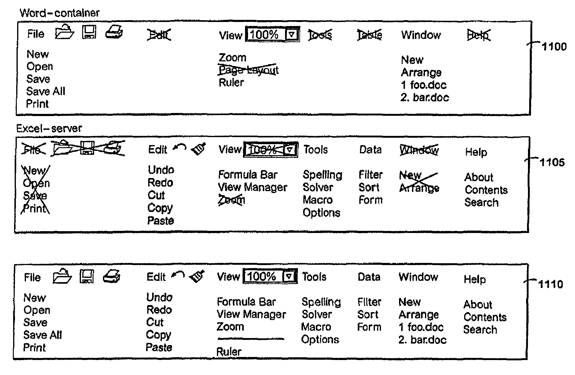
In addition, toolbars were not merged, which resulted in only those toolbars provided by the embedded object being displayed and the controls representing client-type functions (e.g., print) being disabled.
This results in several drawbacks.
First, some useful commands may be not be available while the embedded object is activated.
In addition, some of the available commands may not be useful or intuitive.
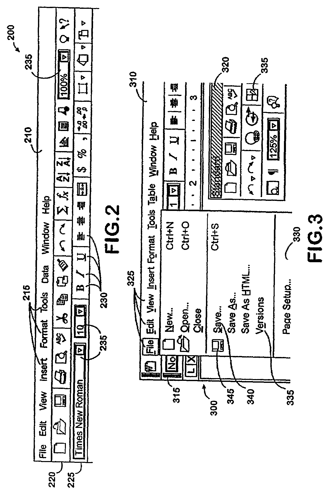
However, the prior art method did not include any visual cue that a menu could be torn off, and was therefore not easily discoverable.
In addition, these menus are prone to being torn off accidentally if the user tries to close the window by the common practice of moving the cursor beyond the window border and releasing the mouse button.
However, there are several disadvantages that flow from the fact that drop down menus and toolbars are treated differently, and may include different controls.
Furthermore, menu merging has been limited to menus, and requiring an application to contribute an entire menu has resulted in the unavailability of some useful commands.

Method used


Image

  • Method for displaying controls in a system using a graphical user interface
  • Method for displaying controls in a system using a graphical user interface
  • Method for displaying controls in a system using a graphical user interface

Examples


Embodiment Construction

[0034]The present invention is directed to an improved method for displaying various controls in command bars, which may be displayed as both popup menu-like containers and toolbar-like containers. The controls, which are associated with a single list of available commands, may be included and arranged in either type of command bar container, regardless of whether the controls are popup menu controls or pushbutton controls (e.g., text, buttons, or other rich controls). When an application embeds an object in another application, each application contributes individual commands to the merged command bars and arranges then in a useful, intuitive order. In addition, some popup controls can be torn off to create separate, floating command bars. The tearable popup controls include visual clues that the menu can be torn off.

[0035]Referring now to the drawings, in which like numerals represent like elements throughout the several figures, aspects of the present invention and an exemplary o...


PUM


Abstract

In a computer employing a graphical user interface (GUI), a method for displaying controls in command bars, which replace conventional menu bars and toolbars. Command bars employ a unified data structure that allows all types of controls to be included in both menu-like command bars and toolbar-like command bars. Command bars may be customized by dragging controls from a list of available commands or from another command bar. By not restricting the types of controls that can appear in each command bar, controls may be grouped to associate drop down menu controls with pushbutton controls. Menu-like command bars and toolbar-like command bars may be merged in a way that provides an intuitive and advantageous listing of commands. Menu popups may be torn off using a clearly indicated drag handle.

Description

[0001]This application is a continuation of application Ser. No.: 08 / 891,945, filed Jul. 14, 1997 now U.S. Pat. No. 6,384,849, which is expressly incorporated herein by reference.TECHNICAL FIELD[0002]The present invention relates to the display and manipulation of command-related items in a graphical operating system, and more particularly relates to an improved method for displaying and manipulating various controls in a system that uses a graphical user interface.BACKGROUND OF THE INVENTION[0003]Most modern computer software employs a graphical user interface (GUI) to convey information to and receive commands from users. A graphical user interface relies on a variety of GUI objects or controls, including icons, text, drop down menus, toolbars, dialog boxes, buttons, and the like. A user typically interacts with a graphical user interface by using a pointing device (e.g., a mouse) to position a pointer or cursor over an object and “clicking” on the object. An example of an operati...

Claims


Application Information

Patent Timeline
IPC IPC(8): G06F13/00G06F9/44
CPCG06F9/4443G06F9/451
Inventor MORCOS, PETER G.AGRAWAL, RAVINDRA K.BALDWIN, LAWRENCE W.HOEK, TJEERD S.PARKER, DAVID C.
Owner MICROSOFT CORP
Learn More