Fault detection and isolation in an optical network

a fault detection and fault isolation technology, applied in the field of fault detection and fault isolation in optical networks, can solve the problems of optical network failure, loss of huge quantities of information, and inability to transmit light between nodes,

Inactive Publication Date: 2006-05-16
CIENA
View PDF18 Cites 34 Cited by
  • Summary
  • Abstract
  • Description
  • Claims
  • Application Information

AI Technical Summary

Benefits of technology

[0015]The present invention generally comprises a fault detection and isolation system and method for optical networks. One aspect of the present invention is that a local controller in each node makes decisions on whether to activate fault restoration elements within the node, eliminating the need for a central computer to coordinate the actions of each node in response to a fault.

Problems solved by technology

Optical networks transport large flows of information such that system outages of even a few seconds can cause the loss of huge quantities of information.
Optical networks can fail due to several different mechanisms.
Line failure is commonly defined as a fault in the ability of light to be transmitted between nodes along a working fiber, i.e., there is no light coupled into the node because of damage to the optical fiber.
Additionally, a line failure can occur at or near the interface of the fiber and a node.
For example, the optical fiber may not be properly inserted into the node.
Additionally, a failure of an optical interface element may be optically equivalent to a line fault if it results in a total loss of signal at all channel wavelengths to all downstream components.
For example, a fault in the optical interface element receiving signals from the fiber that results in a complete loss of signal to all subsequent optical elements within the node is equivalent in effect to a fault in the fiber.
An electrical equipment failure may result in a loss in all channels, but may more commonly result in only a limited number of channels being dropped.
First, it can take a significant length of time for a central computer of a NMS 120 to determine an appropriate course of action due to the cumulative time delays of the system.
There is also a time delay associated with the circuitry at the node that is used to implement a line switch or an equipment switch.
Network outages in excess of 0.1 seconds may therefore cause an irreparable loss of data to a tributary network.
Another drawback of network 100 is that the NMS 120 can be comparatively expensive to implement.
The central computer is often implemented as a high performance work station, which is comparatively expensive.
Another substantial cost is associated with the OEO modules used to measure channel strength in each node 105.
OEO modules increase with cost as a function of the number of optical channels that they are capable of analyzing.
Additionally, the cost of each OEO module tends to increase with the data capacity of each channel since faster optical and electrical components are required for high data rate channels.
This results in a corresponding increase in the cost of the OEO modules compared with first generation WDM designs having three to five moderate data-rate channels.
Another drawback of network 100 is that it may provide insufficient information to isolate electrical equipment failures for later repair.
A single OEO module is typically insufficient to determine the element within a node that has dropped a channel.
Consequently, several OEO modules may be required for fault isolation, further increasing the cost of the system.

Method used


Image

  • Fault detection and isolation in an optical network
  • Fault detection and isolation in an optical network
  • Fault detection and isolation in an optical network

Examples


Embodiment Construction

[0032]The figures depict a preferred embodiment of the present invention for purposes of illustration only. One of skill in the art will readily recognize from the following discussion that alternative embodiments of the structures and methods disclosed herein may be employed without departing from the principles of the claimed invention.

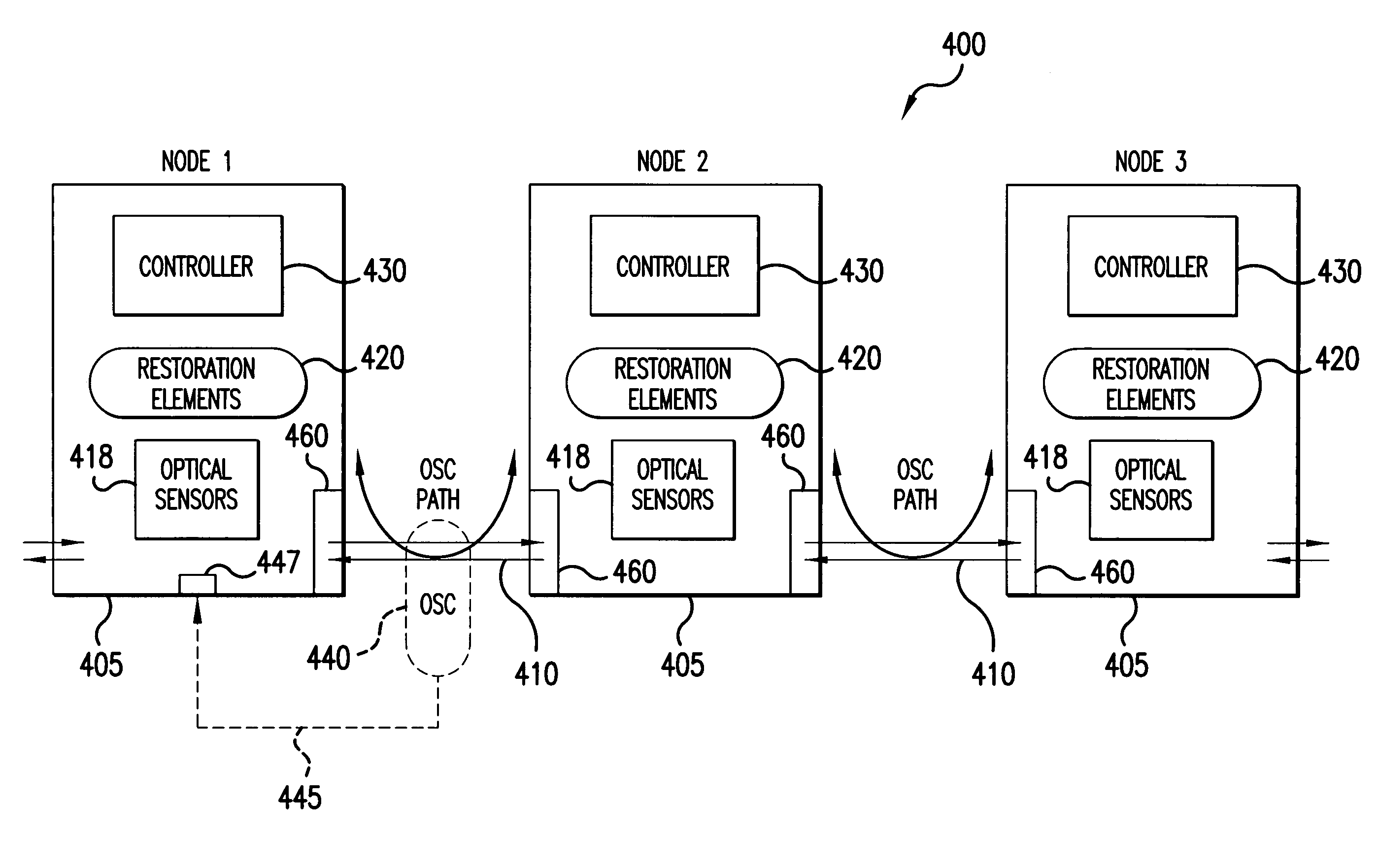
[0033]FIG. 4 is a block diagram of a portion of an optical network 400 illustrating some of the general principles of the present invention. For the purposes of illustration many conventional elements used in optical networks are omitted. It will also be understood that optical network 400 may be part of a larger chain, branched chain, mesh, or ring network. A plurality of network optical nodes 405 are shown coupled by fiber spans 410. The fiber spans 410 may comprise one or more optical fiber lines that include all of the potential optical channel data links between neighboring nodes for communicating an optical datastream. For the purposes of illu...


PUM


Abstract

An apparatus and method for fault detection and isolation in an optical network is disclosed in which each node determines an appropriate response to a line fault or an equipment fault, obviating the need for a central computer to coordinate the actions of each node in response to a fault. Each network node includes a local controller and restoration elements for detecting and responding to faults. Each local controller correllates a first set of optical characteristics measured by optical detectors with the local node with a second set of optical characteristics for the channels reported to the local node from an upstream optical element, such as a neighboring upstream node, to determine if a line switch or equipment switch is required. In a preferred embodiment, each node is communicatively coupled to its neighboring node via an optical supervisory channel, with the neighboring nodes communicating status messages and data on channel characteristics via the optical supervisory channel.

Description

RELATED APPLICATIONS[0001]This application claims the benefit of U.S. provisional application Ser. No. 60 / 152,138, “Fault Detection And Isolation In An Optical Network,” by inventors Kevin Hester, Todd Beine, Rainer Iraschko, and Kent Rhyorchuk, filed Aug. 24, 1999, the entire contents of which are hereby incorporated by reference.BACKGROUND OF THE INVENTION[0002]1. Field of the Invention[0003]The present invention relates generally to fault detection and fault isolation in an optical network.[0004]2. Description of Background Art[0005]Optical data networks typically include a plurality of nodes linked by optical fibers into a network. The network may be one of several common topologies, such as a linear chain network, an optical star network, or an optical ring network. Optical networks are also classified by the geographic size of the network, with wide area networks (WANs) and metropolitan area networks (MANs) being of increasing interest for providing high bandwidth network data...

Claims


Application Information

Patent Timeline
IPC IPC(8): H04B10/08
CPCH04B10/0771
Inventor HESTER, STEWART KEVINBEINE, TODDIRASEHKO, RAINER ROBERTRYHORCHUK, KENT WILFRED GEORGE
Owner CIENA
Why Eureka
Try Eureka