
Instrument with colorimeter and sensor inputs for interfacing with a computer

Active Publication Date: 2006-05-16
MICROLAB
View PDF3 Cites 38 Cited by
  • Summary
  • Abstract
  • Description
  • Claims
  • Application Information

AI Technical Summary

Benefits of technology

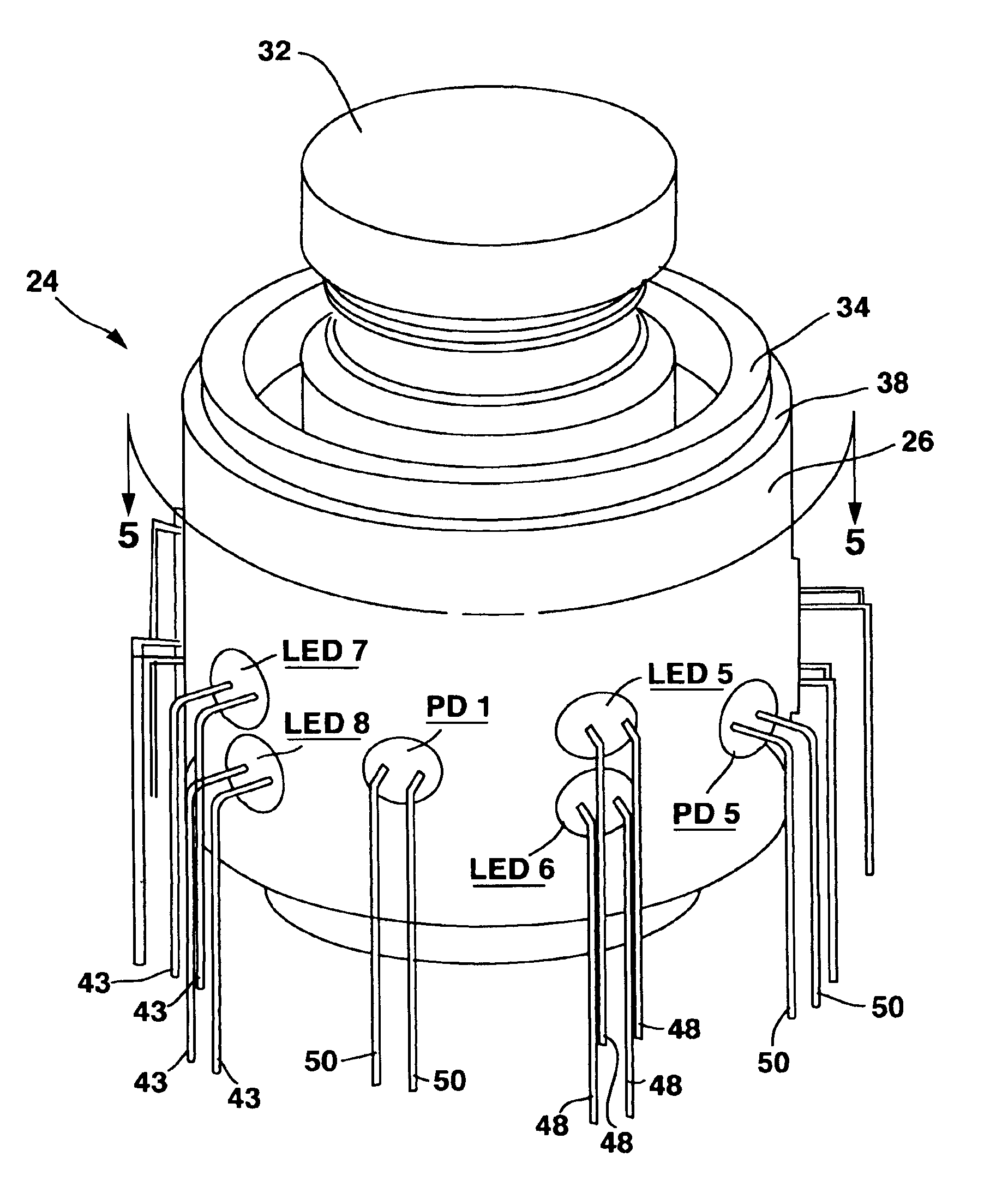
[0008]An array of multiple light-emitting diodes each having a different wavelength are equally spaced around a tubular sample holder facing inwardly. A photo-diode light sensor that detects light transmitted through the sample is mounted to the tubular sample holder at a position directly opposite each light-emitting diode. By selectively turning on one of the LED's and selecting the associated photo-diode exactly opposite it, the light transmission through a solution can be ascertained. A computer is then used to plot the transmission and absorption on a graph for each of the different wavelengths. The circular array of sensors and LED's results in one sensor directly opposite each LED, one sensor off-axis on either side in the forward scatter direction, and one sensor off-axis on either side in the back scatter direction. The combination of back-scattered light and forward-scattered light and transmitted light permits measurements of the turbidity of the sample solution.

Problems solved by technology

The prism or diffraction grating requires a relatively expensive calibrated moving mechanical mount, and the small amount of light that reaches the sample often requires sensitive photo detectors, thus placing a relatively high baseline cost on these instruments.
The diode array spectrophotometer is the most flexible and most expensive of the spectrophotometric instrument family.

Method used


Image

  • Instrument with colorimeter and sensor inputs for interfacing with a computer
  • Instrument with colorimeter and sensor inputs for interfacing with a computer
  • Instrument with colorimeter and sensor inputs for interfacing with a computer

Examples


Embodiment Construction

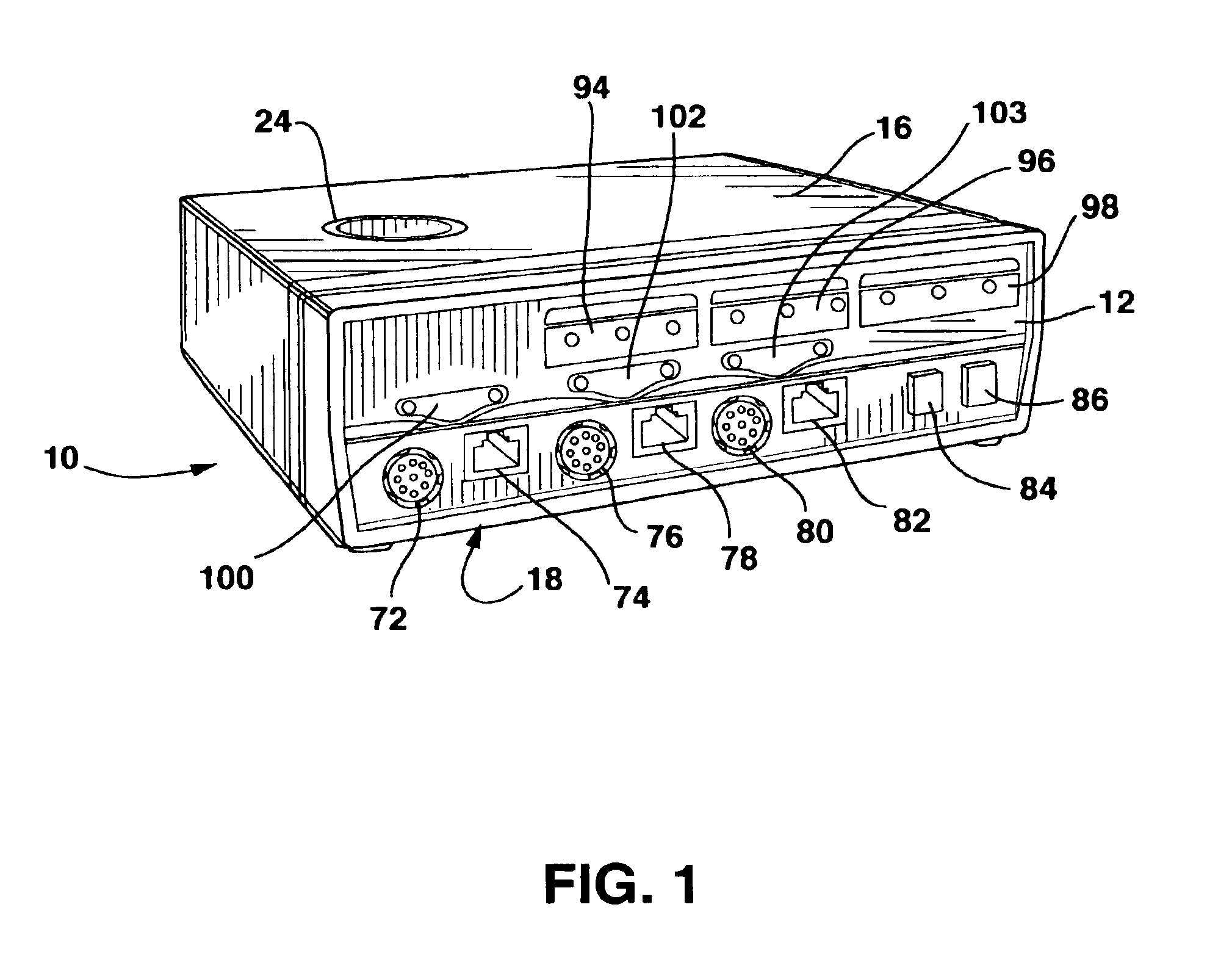
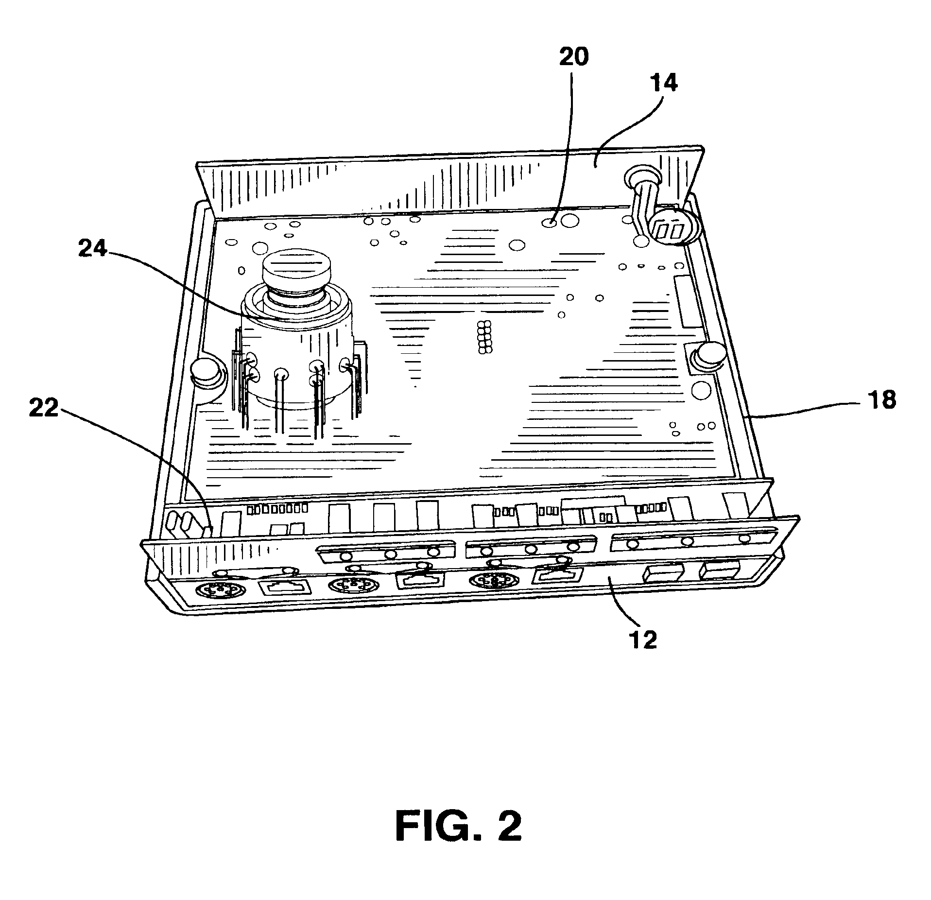
[0018]A diode array colorimeter instrument 10 according to the present invention is shown in FIGS. 1-7. Instrument 10 includes a front panel 12, a rear panel 14, a top cover 16 extending partially down the sides of instrument 10 as shown in FIG. 1, and a bottom cover 18 extending partially up the sides to meet and abut the top cover 16 as shown in FIGS. 2 and 3. A main circuit board 20 is installed within the instrument 10, as shown in FIGS. 2 and 3, and a circuit board 22 for controlling the front panel display is installed within instrument 10, as shown in FIGS. 2 and 3.

[0019]A diode array test sample holder 24 is mounted to circuit board 20 as shown in FIGS. 2 and 3. Test sample holder 24 in includes a tubular body 26, as shown in FIG. 4, extending around a longitudinal axis 28, as shown in FIG. 6, with a hollow interior 30. The hollow interior 30 is sized to accept a transparent cylindrical vial 32, as shown in FIG. 4.

[0020]The body 26 of sample holder 24 includes an upper annul...


PUM


Abstract

An array of multiple light-emitting diodes each having a different wavelength are equally spaced around a tubular sample holder facing inwardly. A photo-diode light sensor that detects light transmitted through the sample is mounted to the tubular sample holder at a position directly opposite each light-emitting diode. By selectively turning on one of the LED's and selecting the associated photo-diode exactly opposite it, the light transmission through a solution can be ascertained. A computer is then used to plot the transmission and absorption on a graph for each of the different wavelengths. The circular array of sensors and LED's results in one sensor directly opposite each LED, one sensor off-axis on either side in the forward scatter direction, and one sensor off-axis on either side in the back scatter direction. The combination of back-scattered light and forward-scattered light and transmitted light permits measurements of the turbidity of the sample solution.

Description

SPECIFICATION[0001]This application claims the benefit of Provisional Application Ser. No. 60 / 280,674, filed Mar. 30, 2001.BACKGROUND OF INVENTION[0002]This invention relates to a diode array colorimeter instrument for measuring light transmission through a test sample and for measuring the turbidity of the test sample.[0003]Colorimetry and spectrophotometry, analytical techniques based on passing light through a colored solution, are the most widely chemical used analysis method in medicine, chemistry, water quality, and environmental science. Spectrophotometry involves relatively high cost instruments that use a continuously variable wavelength of light of quite narrow bandwidth, while colorimetry involves lower cost instruments with several selectable wavelengths or colors and wider bandwidth. Colored solutions absorb certain wavelengths of light because of electron energy level spacings within the absorbing molecule. Absorption of a specific wavelength of light is related to the...

Claims


Application Information

Patent Timeline
IPC IPC(8): G01J3/50G01N21/49
CPCG01J3/0264G01J3/0291G01N21/31G01N21/51
Inventor AMEND, JOHN R.HAMMOND, DALE A.
Owner MICROLAB
Learn More