
Apparatus and method for servo control of an aircraft

a technology of servo amplifier and aircraft, which is applied in the direction of coupling, slip coupling, gearing, etc., can solve the problems of insufficient torque capacity of dc servomotor and servo amplifier, inability to provide disconnect, and insufficient torque capacity of stepping motor, etc., to improve the safety of operation, improve the control of the aircraft, and improve the effect of operation efficiency

Inactive Publication Date: 2006-05-16
HONEYWELL INT INC
View PDF14 Cites 16 Cited by
  • Summary
  • Abstract
  • Description
  • Claims
  • Application Information

AI Technical Summary

Benefits of technology

[0013]In brief, the present invention is an autopilot servo and method for using an autopilot servo that has a compact and efficient architecture to better control an aircraft, and in particular, an aircraft which may carry passengers.
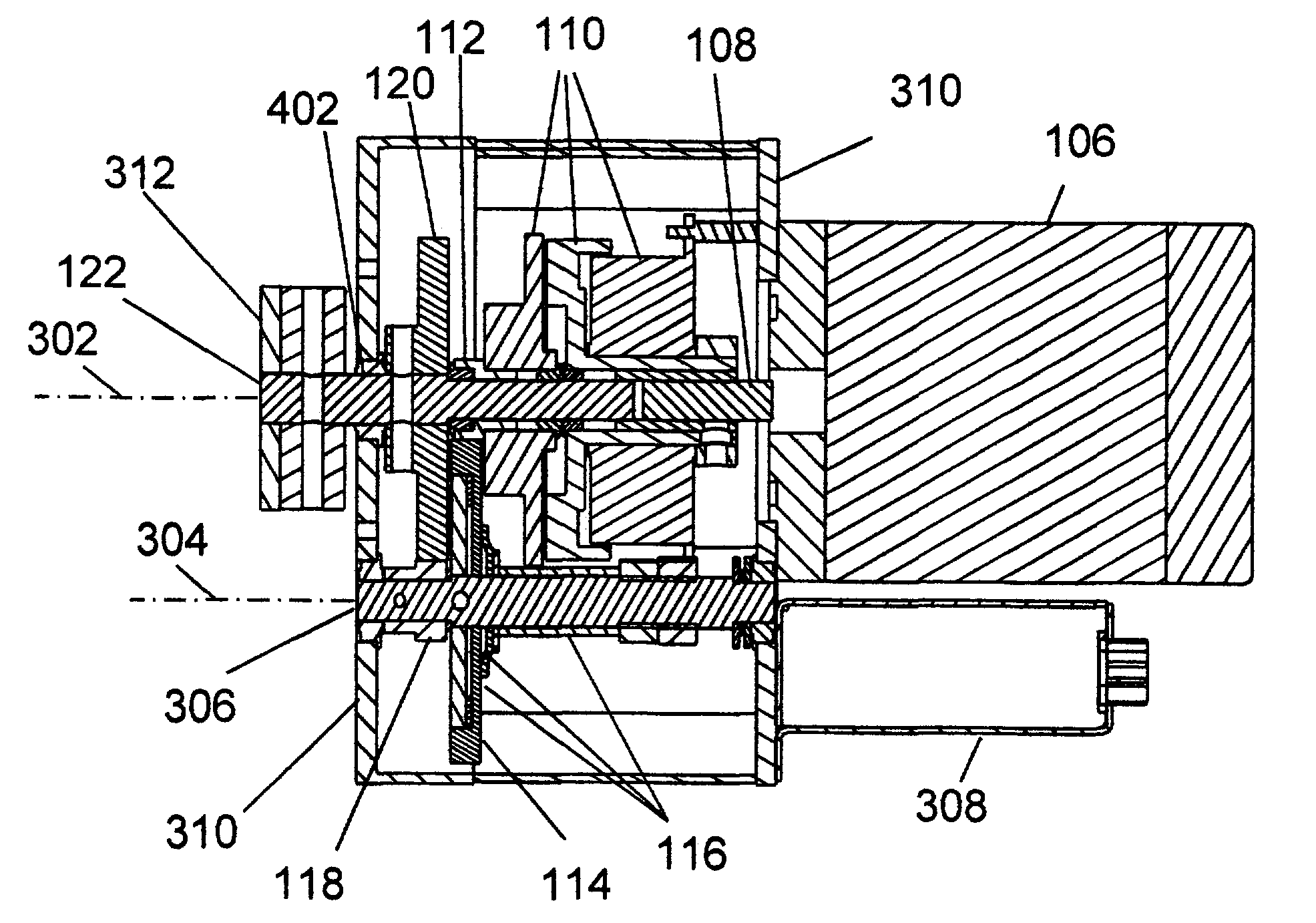
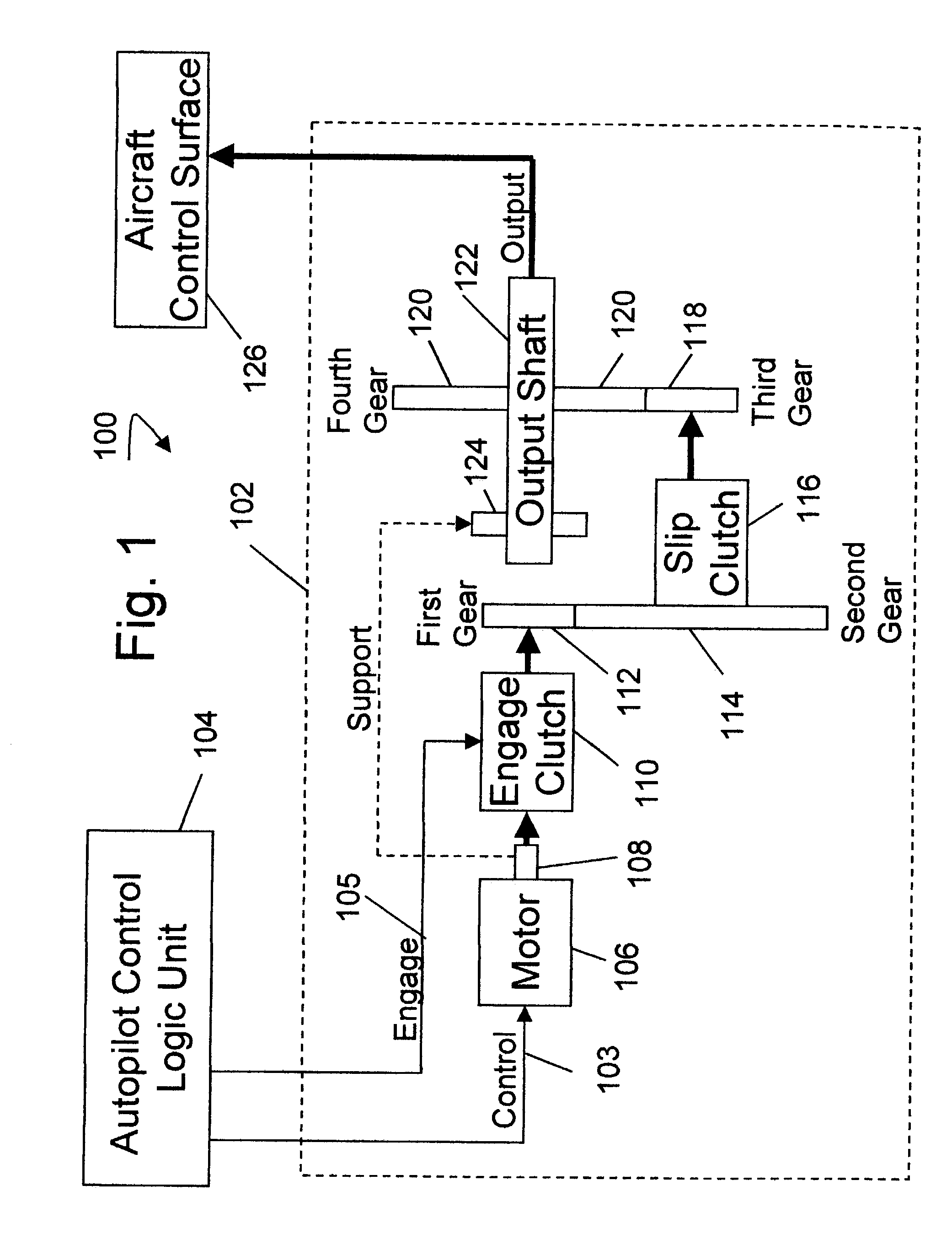
[0014]In accordance with the present invention, autopilot control of an aircraft is accomplished using a servo wherein the input shaft and output shaft are collinear. In one embodiment, the output shaft is supported, in part, by the input shaft. In further embodiments an engage clutch mechanism is provided to allow decoupling of the motor from the output shaft, and a slip clutch mechanism is provided to limit the torque output of the servo to enhance the safety of operation. The collinear shaft arrangement enables the engage clutch mechanism and slip clutch mechanism to synergistically utilize components for multiple functions thereby reducing complexity and saving space and weight.
[0015]Included in the many advantages and features of the invention are superior safety, economy, ease of installation and interface with the autopilot control logic unit. These and other features and advantages will become apparent as the particular embodiments are more fully described in the following detailed description and accompanying drawings.

Problems solved by technology

This typically results in a requirement for several independent ways to remove or decouple the servo from the aircraft control mechanism.
However, these DC servomotors and servo amplifiers are frequently too large or fall short on one or more of the features needed by the digital autopilot.
However, the torque capacity of these stepping motors is insufficient for some applications and no disconnect is provided.

Method used


Image

  • Apparatus and method for servo control of an aircraft
  • Apparatus and method for servo control of an aircraft
  • Apparatus and method for servo control of an aircraft

Examples


Embodiment Construction

[0026]The present invention will now be described more fully in detail with reference to the accompanying drawings, in which the preferred embodiments for the invention are shown. This invention should not, however, be construed as limited to the embodiments set forth herein; rather, these embodiments are provided so that this disclosure will be thorough and complete and will fully convey the scope of the invention to those skilled in the art. Like numbers refer to like elements throughout.

[0027]In brief, the present invention is an autopilot servo and method for using an autopilot servo that has a compact and efficient architecture to better control an aircraft and is particularly directed to aircraft which may carry passengers. Included in the many advantages and features of the invention are superior safety, economy, ease of installation and ease of interface with an autopilot controller.

[0028]The servo architecture achieves efficiency in design and production by placing the comp...


PUM


Abstract

Autopilot control of an aircraft is accomplished using a servo wherein the input shaft and output shaft are collinear. In one embodiment, the output shaft is supported, in part, by the input shaft. In further embodiments an engage clutch mechanism is provided to allow decoupling of the motor from the output shaft, and a slip clutch mechanism is provided to limit the torque output of the servo to enhance the safety of operation. The collinear shaft arrangement enables the engage clutch mechanism and slip clutch mechanism to synergistically utilize components for multiple functions.

Description

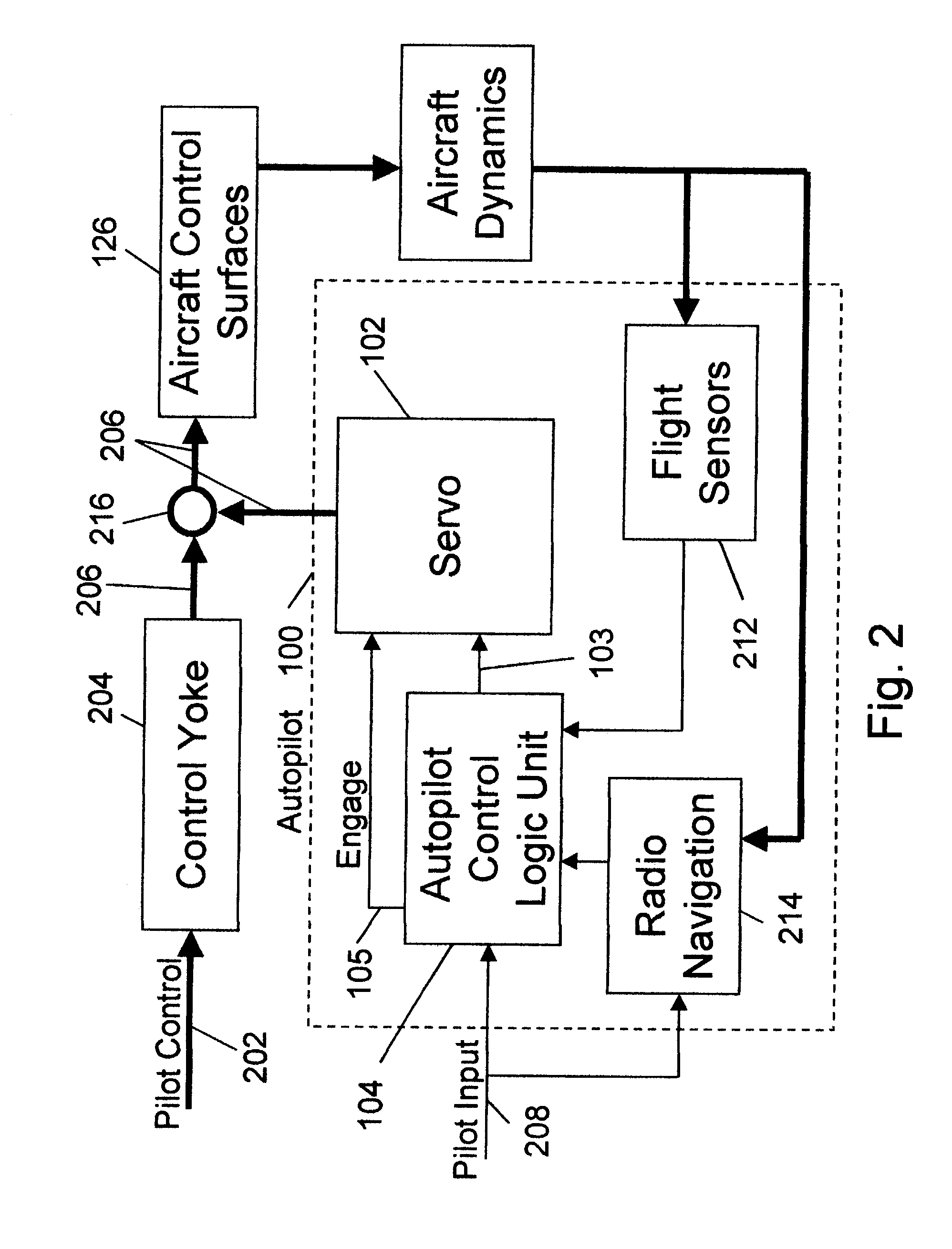
BACKGROUND OF THE INVENTION[0001]1. Field of the Invention[0002]The present invention relates in general to the field of autopilot control systems, and more specifically, to the field of servo control devices that can automatically control an aircraft.[0003]2. Background of the Related Art[0004]An autopilot for a typical small, piloted aircraft is an aid to the pilot and functions to reduce the pilot's workload, reducing fatigue and enabling the pilot to concentrate on other tasks such as navigating, checking the instruments, or simply enjoying the flight. Such autopilots may handle only one axis, such as heading, or may handle all control surfaces and may be coupled, as desired, to radio or GPS navigation aids to enable fully automated control between or among one or more geographical points according to a preset plan.[0005]A typical autopilot includes a control logic unit that receives pilot commands and interfaces with flight sensors and possibly radio navigation systems. In some...

Claims


Application Information

Patent Timeline
Patent Type & Authority Patents(United States)
IPC IPC(8): F16H37/06
CPCB64C13/24F16D7/025F16D27/112F16D47/02F16D48/06Y10T74/19051Y02T50/44Y10T74/19219Y10T74/19223F16D2500/50287F16D2500/51F16D2500/7041F16D2500/7044Y02T50/40
Inventor YOUNKIN, JAMES R.
Owner HONEYWELL INT INC
Learn More