
Pressure sensor device having temperature sensor

Active Publication Date: 2006-05-16
DENSO CORP
View PDF17 Cites 34 Cited by
  • Summary
  • Abstract
  • Description
  • Claims
  • Application Information

AI Technical Summary

Benefits of technology

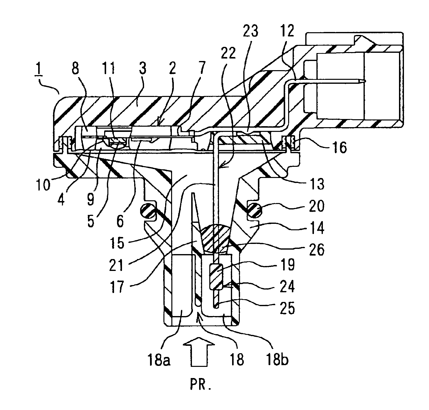
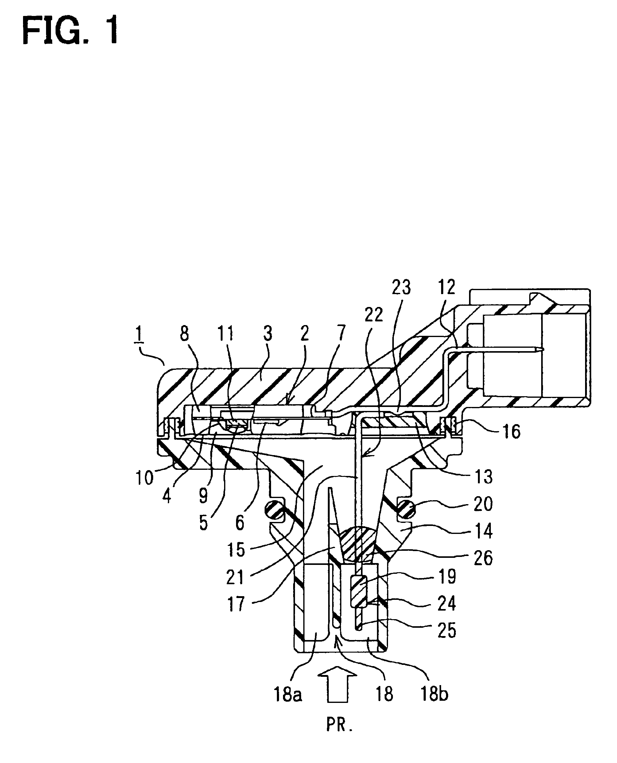
[0007]A pressure sensor device having a temperature sensor includes a pressure sensor for detecting pressure of a measuring object, a temperature sensor for detecting temperature of the measuring object, a sensor casing for accommodating the pressure sensor and a connector pin, which electrically connects the pressure sensor and an outside circuit, a port mounted on the sensor casing and having a pressure introduction port for introducing the measuring object to the pressure sensor disposed in the sensor casing, and a vibration reduction means for reducing a vibration of both the temperature sensor and the lead wire. The temperature sensor is disposed in the pressure introduction port, and electrically connects to the connector pin through a lead wire. Both the temperature sensor and the lead wire are supported by a connection portion, which is disposed between the connector pin and the lead wire.
[0008]In the above device, the vibration of the lead wire with the temperature sensor is reduced by the vibration reduction means even when a vibration is applied to the device. Thus, endurance of the device is improved.
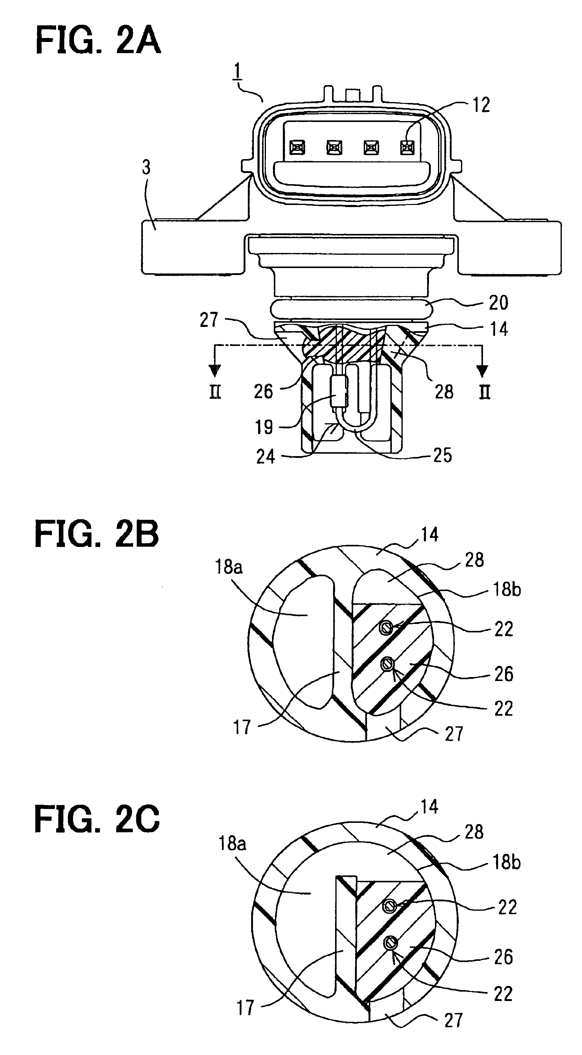
[0010]Preferably, the pressure introduction port includes a partition plate for separating at least a part of the pressure introduction port into two parts. The partition is disposed along with an introducing direction of the measuring object. One part of the pressure introduction port is a temperature sensor chamber for accommodating the temperature sensor. In this case, the buffer is easily inserted between the lead wire and a part of the pressure introduction port.
[0011]Preferably, the vibration reduction means is provided such that at least one of the temperature sensor or the lead wire is insert-molded into the port so as to reduce the vibration. More preferably, both the sensor casing and the port provide a pressure chamber for introducing the measuring object therein, and the lead wire and the connector pin are connected at a connection portion, which is disposed outside the pressure chamber. In this case, at least one of the lead wire or the temperature sensor is integrated into the port so that both the lead wire and the temperature sensor are preliminarily positioned at a predetermined position. Therefore, the lead wire and the connector pin can be connected at the outside of the pressure chamber, so that the connection portion is not contaminated. Thus, a protection for the connection portion can be formed of epoxy resin or silicon resin, which has less chemical resistance but less expensive.
[0012]Further, a pressure sensor device having a temperature sensor includes a pressure sensor, a temperature sensor attached to a lead wire, a casing for accommodating the pressure sensor and a connector pin for connecting both the pressure sensor and the temperature sensor to an outside circuit, a passage disposed in the casing for introducing a measuring object to the pressure sensor, and a vibration reduction means for reducing a vibration of the lead wire with the temperature sensor. The lead wire is supported by a connection portion between the connector pin and the lead wire so that the lead wire is protruded in the port.
[0013]In the above device, the vibration of the lead wire with the temperature sensor is reduced by the vibration reduction means even when a vibration is applied to the device. Thus, endurance of the device is improved.

Problems solved by technology

Moreover, even when a contamination contaminated into the pressure introduction port, the contamination is discharged through the buffer together with the measuring object flowing therethrough.

Method used


Image

  • Pressure sensor device having temperature sensor
  • Pressure sensor device having temperature sensor
  • Pressure sensor device having temperature sensor

Examples


first embodiment

(First Embodiment)

[0022]A pressure sensor device 1 having a temperature sensor according to a first embodiment of the present invention is shown in FIG. 1. The pressure sensor device 1 detects, for example, both pressure and temperature of intake air as a measuring object in an intake manifold of a vehicle. The device 1 includes a sensor casing 3. A mold IC (i.e., integrated circuit) 2 as a pressure detection element having a pressure sensor chip 5 is disposed in the sensor casing 3. The mold IC 2 includes a fixation portion 4 having a concavity, in which the pressure sensor chip 5 is mounted. The pressure sensor chip 5 detects the pressure of the measuring object. The mold IC 2 further includes a signal processor IC 6 and a lead frame 7.

[0023]The signal processor IC 6 magnifies a measurement signal outputted from the pressure sensor chip 5. The lead frame 7 outputs a magnified measurement signal from the signal processor IC 6. The signal processor IC 6 and the lead frame 7 are mold...

second embodiment

(Second Embodiment)

[0044]A pressure sensor device 200 having a temperature sensor according to a second embodiment of the present invention is shown in FIG. 3. The lead wire 22 of the temperature sensor 24 follows the inner wall of the temperature sensor chamber 18b. An elastic member 29 having a ball shape is disposed in the temperature sensor chamber 18b so that the elastic member 29 suppresses the vibration of the lead wire 22. The elastic member 29 is inserted into the temperature sensor chamber 18b through the introduction port 27. At this time, the elastic member 29 deforms so as to be inserted into the temperature sensor chamber 18b. The elastic member 29 is disposed between the lead wire 22 and the inside end of the introduction port 27, so that the lead wire 22 is press-contacted to the inner wall of the temperature sensor chamber 18b. Thus, the vibration of the temperature sensor 24 is reduced. The elastic member 29 does not have fluidity such as the resin material, so tha...

third embodiment

(Third Embodiment)

[0049]A pressure sensor device 300 having a temperature sensor according to a third embodiment is shown in FIG. 4. At least one of the temperature sensor chip 19 or the lead wire 22 is insert-molded into the inlet port 14. Therefore, the temperature sensor 24 is supported by both the inlet port 14 and the connection portion 23, so that the vibration of the temperature sensor 24 is reduced. Accordingly, the endurance of the temperature sensor 24 is increased.

[0050]Although the lead wire 22 of the temperature sensor 24 is inserted into the inlet port 14, both the temperature sensor chip 19 and the lead wire 22 are inserted into the inlet port 14. In this case, since the temperature sensor chip 19 detects the temperature through the inner wall of the inlet port 14, the response of the temperature sensor chip 19 is reduced. Therefore, it is preferred that the temperature sensor 24 is inserted into the inlet port 14 so as to detect the temperature directly by the temper...


PUM


Abstract

A pressure sensor device having a temperature sensor includes a pressure sensor, a temperature sensor, a sensor casing for accommodating the pressure sensor and a connector pin for electrically connecting the pressure sensor and an outside circuit, and a port mounted on the sensor casing and having a pressure introduction port for introducing a measuring object to the pressure sensor. The temperature sensor is disposed in the pressure introduction port, and electrically connects to the connector pin through a lead wire. The lead wire with the temperature sensor is supported by a connection portion disposed between the connector pin and the lead wire. The lead wire has a buffer disposed between the lead wire and a part of the pressure introduction port for reducing a vibration of both the temperature sensor and the lead wire.

Description

CROSS REFERENCE TO RELATED APPLICATION[0001]This application is based on Japanese Patent Applications No. 2002-308982 filed on Oct. 23, 2002, and No. 2003-75019 filed on Mar. 19, 2003, the disclosures of which are incorporated herein by reference.FIELD OF THE INVENTION[0002]The present invention relates to a pressure sensor device for detecting pressure of a measuring object, and more particularly to a pressure sensor device having a temperature sensor for detecting both pressure and temperature of the measuring object.BACKGROUND OF THE INVENTION[0003]A pressure sensor device having a temperature sensor, i.e., the pressure sensor device integrated with the temperature sensor, is, for example, used for a vehicle. The device detects both pressure and temperature of intake air as a measuring object in an intake manifold of the vehicle, so that the device outputs a measurement signal to a controller. The controller calculates and outputs a control signal to an engine of the vehicle so t...

Claims


Application Information

Patent Timeline
IPC IPC(8): G01L19/04G01L19/06F02B77/00G01K1/14G01K7/00G01K7/22G01L19/00G01L19/02G01L23/24
CPCG01K7/22G01L19/0092G01L19/02G01L23/24G01K2205/02H01L2924/0002H01L2924/00
Inventor HAYASHI, KYUTAROSAITOU, TAKASHIGEKATO, YUKIHIRO
Owner DENSO CORP
Learn More