Electro-magnetic analysis program of electric rotating machine

a technology of electromagnetic field analysis and electric rotating machines, which is applied in the direction of mechanical roughness/irregularity measurement, nuclear elements, and susceptibility measurement, etc., can solve the problems of inability to independently analyze the electromagnetic field of higher-harmonic components, inability to obtain the electro-magnetic field distribution of each specific higher-harmonic component, and inability to achieve independent electro-magnetic field analysis

Inactive Publication Date: 2006-05-09
HITACHI LTD
View PDF4 Cites 0 Cited by
  • Summary
  • Abstract
  • Description
  • Claims
  • Application Information

AI Technical Summary

Benefits of technology

[0009]An object of the present invention is to provide an electro-magnetic field analysis technique of an electric rotating machine, with which the electro-magnetic field distribution of specific spatial higher-harmonic or time higher-harmonic is displayed so that the designer of the rotating machine can obtain information useful for analyzing the vibration and noise.

Problems solved by technology

With the conventional electro-magnetic field analysis technique of an electric rotating machine, however, the electro-magnetic field distribution obtained through the analysis contains multiple higher-harmonic components and independent electro-magnetic field analysis of higher-harmonic component is not feasible.
In other words, because multiple components are all superimposed in the electro-magnetic field distribution obtained through the conventional electro-magnetic field analysis, there arises a problem that electro-magnetic field distribution by each specific higher-harmonic, which is useful for identifying a troublesome higher-harmonic or examining a measures to reduce the vibration, noise, iron loss or eddy current loss, is not available.

Method used


Image

  • Electro-magnetic analysis program of electric rotating machine
  • Electro-magnetic analysis program of electric rotating machine
  • Electro-magnetic analysis program of electric rotating machine

Examples


first embodiment

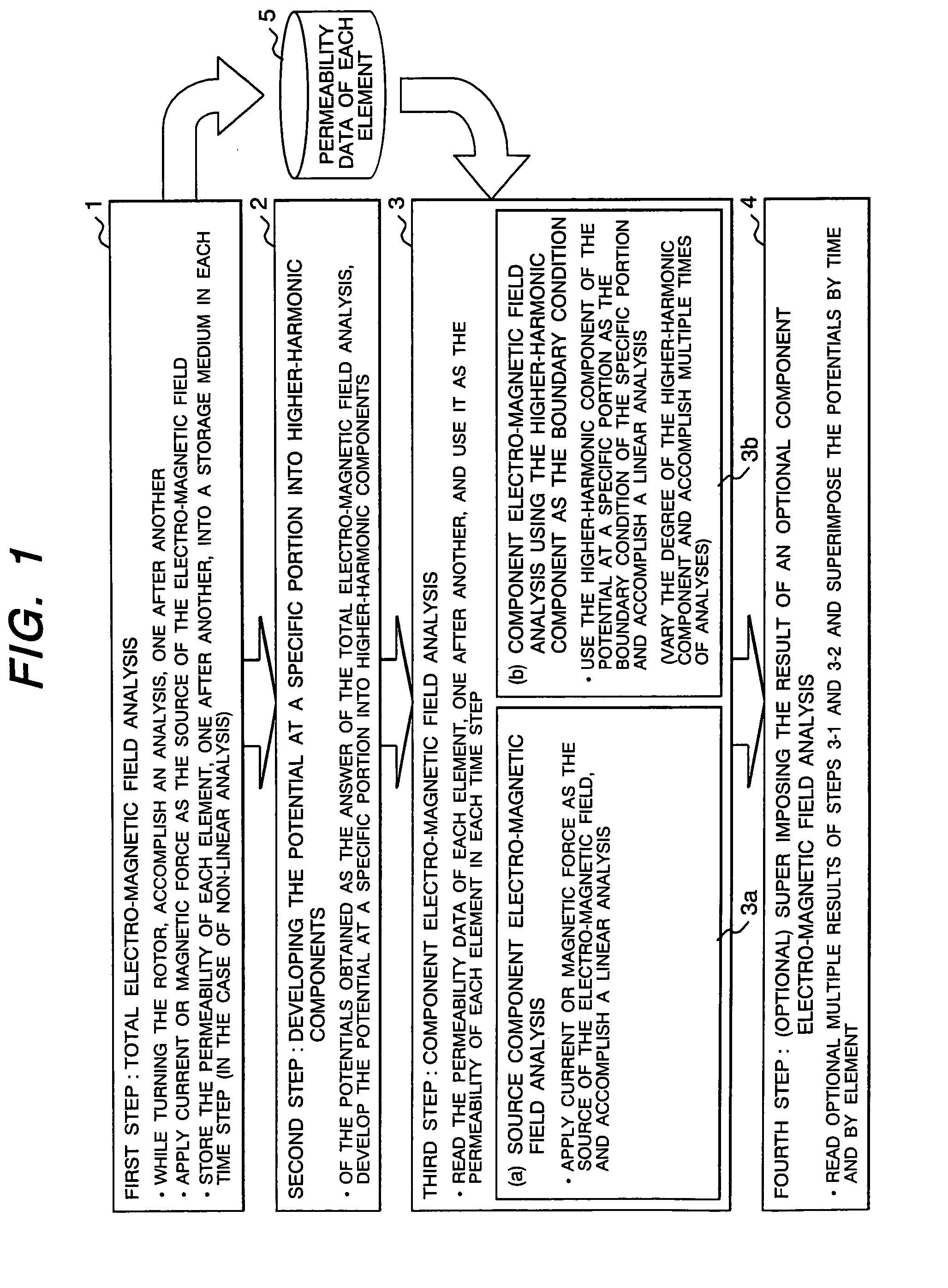
[0036]The electro-magnetic field analysis technique of an electric rotating machine according to the present invention is described hereunder, using figures. To start with, the electro-magnetic field analysis technique according to the present invention is described hereunder, using FIG. 1. As shown in FIG. 1, with the electro-magnetic field analysis technique according to this embodiment, a total electro-magnetic field analysis 1 based on a prior art is accomplished in the first step. In this step, an analysis is accomplished, one after another, by the time-stepping technique while turning the rotor at the number of revolutions specified as a computation condition. A magneto-motive force by current or magnet is applied as the source of the electro-magnetic field. In the case of non-linear analysis with consideration given to non-linear electro-magnetic characteristic, the permeability data 5 of each element is saved or stored in each time step. In the second step, of the potentials...

second embodiment

[0039]FIG. 2 shows a flowchart of the electro-magnetic field analysis according to the present invention, and FIG. 3 is a supplemental explanatory figure of the electro-magnetic field analysis of this embodiment. As shown in FIG. 2, the total analysis space 11 comprises an outside peripheral analysis space 12 and inside peripheral analysis space 13, and, with the electro-magnetic field analysis technique of this embodiment, the electro-magnetic field is developed (separated) into both spatial higher-harmonic and time higher-harmonic. Description below is made on an assumption that the total analysis space 11 is a two-dimensional space on a cross-section in the axial direction and the variable for the electro-magnetic field analysis is an axial component of the magnetic vector potential. The outside peripheral analysis space 12 and inside peripheral analysis space 13 represent either the stator side and rotor side, respectively, or the rotor side and stator side, respectively. The ar...

third embodiment

[0054]FIG. 4 shows a flowchart of the electro-magnetic field analysis according to the present invention. The analysis in FIG. 4 differs from that in FIG. 2 in a point that the higher-harmonic handled by the analysis is spatial higher-harmonic only. The total electro-magnetic field analysis 21 is the same as in FIG. 2 and the permeability data of each element is similarly saved. In the spatial higher-harmonic component analysis 25 of the potential a, the potential on the arc bb′, obtained in the total electro-magnetic field analysis 21, is developed into spatial higher-harmonic components as given by Formula (5).

[0055][Formula⁢⁢5]⁢⁢a⁡(θ,t)=A0+∑m⁢Am⁡(t)⁢sin⁡(mθ+αm1⁡(t))(5)

[0056]The electro-magnetic field analysis 23 of leakage magnetic flux of the rotor and stator is the same as in FIG. 2.

[0057]In the specific spatial higher-harmonic electro-magnetic field analysis 26, the permeability data 5 of each element obtained in the total electro-magnetic field analysis 21 is read and assigne...


PUM


Abstract

(Subject)To provide an electro-magnetic field analysis technique of an electric rotating machine that filters through a specific higher-harmonic at a specific portion.(Construction)The first electro-magnetic field analysis procedure of analyzing the electro-magnetic field in an analysis space based on the first boundary condition in terms of an electro-magnetic variable assigned to the first specific portion in the analysis space; a development procedure 2 of developing the electro-magnetic variable at the second specific portion in the analytic space, obtained in the first electro-magnetic field analysis procedure, into each higher-harmonic component; the second boundary condition setting procedure of assigning an electro-magnetic variable in terms of at least one of the higher-harmonic components, developed from the above electro-magnetic variable, to the second specific portion as the second boundary condition; and a procedure 3 of analyzing the electro-magnetic field of the analysis space based on the first and second boundary conditions are executed on a computer.

Description

BACKGROUND OF THE INVENTION[0001]1. (Field of the Invention)[0002]The present invention relates to the electro-magnetic field analysis technique of an electric rotating machine, particularly to the electro-magnetic field analysis technique of an electric rotating machine that can decompose the electro-magnetic field of the electric rotating machine into multiple higher-harmonic components and leakage magnetic flux that comprise the electro-magnetic field distribution.[0003]2. (Prior Art)[0004]A conventional electro-magnetic field analysis of an electric rotating machine employs a time-stepping technique in which the analysis is accomplished step by step as the rotor is turned gradually (for example, see the Non-Patent Document 1).[0005][Non-Patent Document 1][0006]T. W. Preston, A. B. J. Reece and P. S. Sangha: “Induction motor analysis by time-stepping techniques”, IEEE Trans. on Magnetics, vol. 26, No. 2, pp. 551–554, 1990.SUMMARY OF THE INVENTION[0007](Problems to be Solved by th...

Claims


Application Information

Patent Timeline
Patent Type & Authority Patents(United States)
IPC IPC(8): G06F13/10G01R31/34G01R33/10G01R33/16G05B17/02G06F17/50G06F19/00H02K1/04H02K15/00
CPCH02K15/00
Inventor IDE, KAZUMASAMIYATA, KENJISHIMA, KAZUOTANI, MASAYUKI
Owner HITACHI LTD
Why Eureka
Try Eureka