
Linear optical sampling method and apparatus

a sampling method and optical sampling technology, applied in the field of linear optical sampling, can solve problems such as lack of sensitivity, and achieve the effects of low distortion, optimal time resolution, and high sensitivity and temporal resolution

Active Publication Date: 2006-05-09
ALCATEL-LUCENT USA INC +1
View PDF3 Cites 23 Cited by
  • Summary
  • Abstract
  • Description
  • Claims
  • Application Information

AI Technical Summary

Benefits of technology

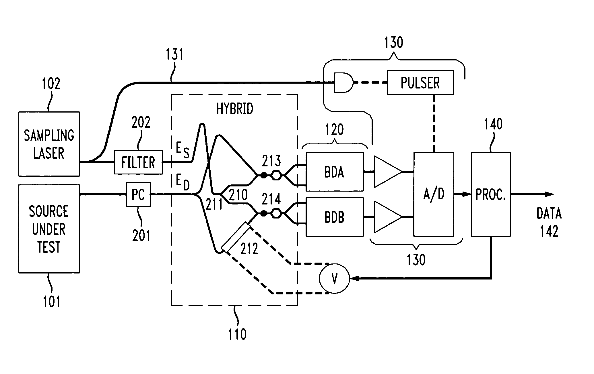
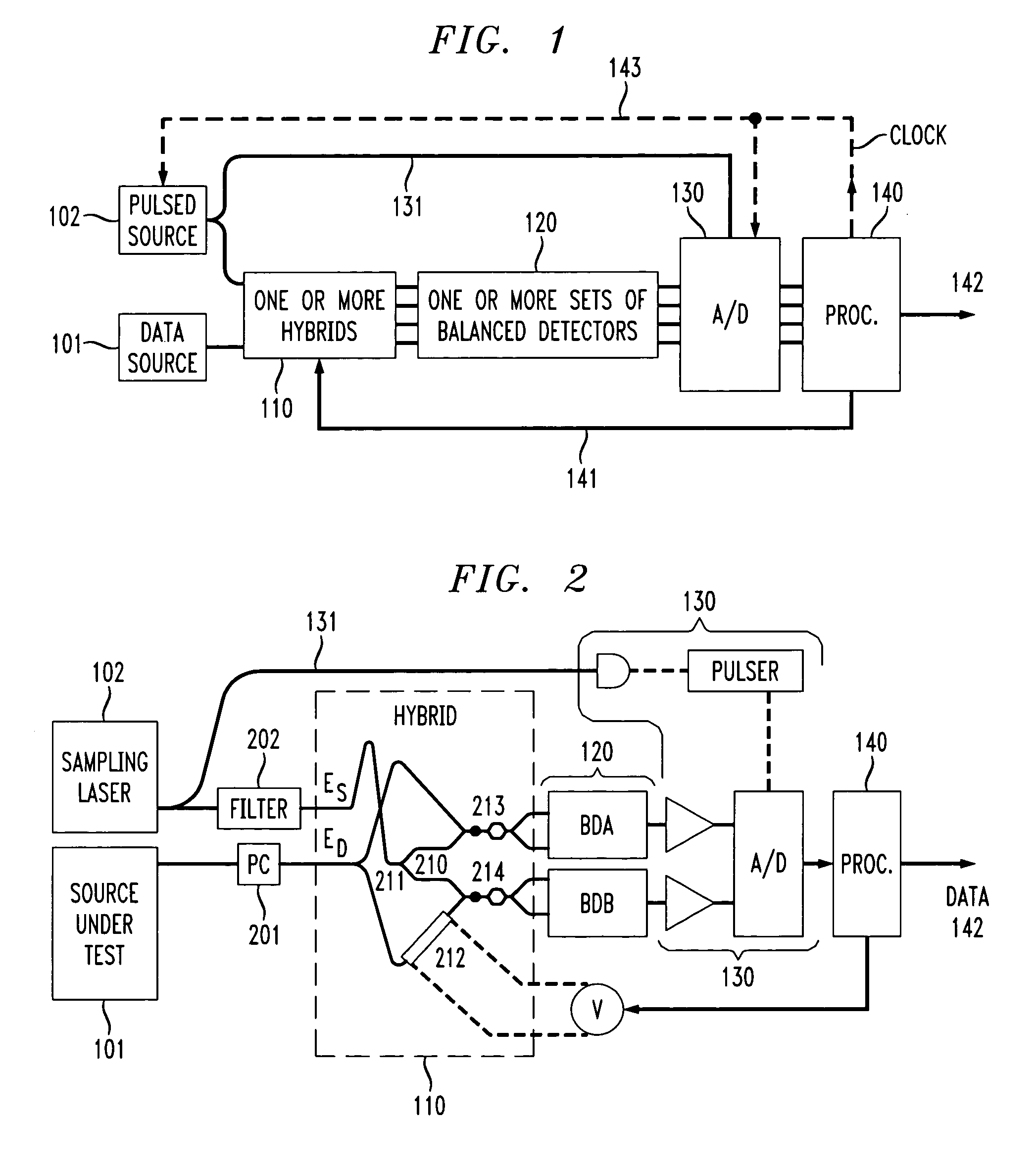
The present invention describes a linear optical sampling apparatus that uses a 90° hybrid to combine two optical signals and measures their interference. The apparatus includes a pulsed optical signal source, a 90° hybrid, balanced photodetectors, sampling analog / digital converters, and a processor to compensate for signal handling imperfections and measure temporal signal samples. The invention also describes a method of operating the optical sampling apparatus and an optical receiver for demodulating data from a data modulated optical signal. The technical effects of the invention include high sensitivity, low distortion, and optimal time resolution.

Problems solved by technology

However, it often lacks sensitivity.

Method used


Image

  • Linear optical sampling method and apparatus
  • Linear optical sampling method and apparatus
  • Linear optical sampling method and apparatus

Examples


Embodiment Construction

1. Linear Optical Sampling

[0037]The following paragraphs summarize the linear optical sampling apparatus described in reference [6] which is incorporated by reference herein. Linear optical sampling temporally characterizes an optical waveform by measuring the amplitude of the interference of its electric field ED(t) with the electric field of a sampling pulse ES(t) using two orthogonal quadratures of the interference. A quadrature SA=real[exp(iφA)·∫ED(t)·ES*(t)dt] can be obtained by combining the two sources optically and performing time-integrated balanced detection on the two outputs of the coupler using low-speed detectors (the temporal integration extends in theory only over the integration time of the detectors, but such time is in practice much longer than the durations of the various pulses, and integration will always be taken from −∞ to +∞ for the sake of simplicity). The constant phase φA describes the optical phase difference between the two fields, and makes the value o...


PUM

PropertyMeasurementUnit
sizeaaaaaaaaaa
sizeaaaaaaaaaa
voltageaaaaaaaaaa

Abstract

A linear optical sampling apparatus, temporally samples a modulated optical signal using the amplitude of the interference of its electric field with the electric field of a laser pulse. The apparatus includes a 90° optical hybrid that combines the optical signal and laser pulse in order to generate two quadratures interference samples SA and SB. A processor compensates for optical and electrical signal handling imperfections in the hybrid, balanced detectors, and A / D converters used in the optical sampling apparatus. The processor numerically scales the two quadratures interference samples SA and SB over a large collection of samples by imposing that the average <SA>=<SB>=0 and <SA2>=<SB2> and then minimizes 2<SA·SB> / (<SA2>+<SB2>) =cos(φB−φA)). This is done by adjusting the phase between the two quadratures (ideally either −π / 2 or +π / 2) so that cos(φB−φA)) is zero. The processor then generates a demodulated sample signal using the quadratures interference samples SA and SB. According to one feature, the hybrid sets the relative phase between two quadratures of their interferometric component so that the phase sensitivity inherent to linear optics is removed. A variety of hybrid arrangements is disclosed that can be implemented using integrated waveguide technology. The apparatus enables sampling of picosecond pulses up to 640 Gb / s with high sensitivity and temporal resolution.

Description

TECHNICAL FIELD OF THE INVENTION[0001]This invention relates generally to linear optical sampling and, more particularly, to a linear optical sampling apparatus including a 90° optical hybrid and a sample scaling processor.BACKGROUND OF THE INVENTION[0002]The temporal characterization of high bit-rate sources is crucial for the development of high-speed optical telecommunications. As direct photodetection and electronic sampling do not have the required bandwidth, such characterization must be performed by taking advantage of the large bandwidth of optical sources. A nonlinear interaction with an ancillary pulse, such as sum-frequency generation, four-wave mixing, cross-phase modulation or two-photon absorption, can be used to provide a temporal gating mechanism with a resolution on the order of the duration of the ancillary pulse [1–5]. (Note, the bracketed references [ ] refer to publications listed in the attached Reference list.) Because sub-picosecond sampling pulses are availa...

Claims


Application Information

Patent Timeline
Patent Type & Authority Patents(United States)
IPC IPC(8): G02F2/00G02F1/01H04B10/06G01J11/00
CPCG01J11/00
Inventor DOERR, CHRISTOPHER RICHARDDORRER, CHRISTOPHE J.WINZER, PETER J.
Owner ALCATEL-LUCENT USA INC
Learn More