
Man machine interfaces and applications

Inactive Publication Date: 2006-05-09
PRYOR TIMOTHY R +1
View PDF13 Cites 758 Cited by
  • Summary
  • Abstract
  • Description
  • Claims
  • Application Information

AI Technical Summary

Benefits of technology

[0036]For degrees of freedom beyond 3, we feel such specialized datum based technology is the only practical method today. Retroreflective glass bead tape, or beading, such as composed of Scotchlite 7615 by 3M co., provides a point, line, or other desirably shaped datum which can be easily attached to any object desired, and which has high brightness and contrast to surroundings such as parts of a human, clothes, a room etc, when illuminated with incident light along the optical axis of the viewing optics such as that of a TV camera. This in turn allows cameras to be used in normal environments, and having fast integration times capable of capturing common motions desired, and allows datums to be distinguished easily which greatly reduces computer processing time and cost.
[0056]The invention is particularly valuable for expanding the value of life-size, near life size, or at least large screen (e.g. greater than 42 inches diagonal) TV displays. Since the projection can now be of this size at affordable cost, the invention allows an also affordable means of relating in a lifelike way to the objects on the screen—to play with them, to modify them, and other wise interrelate using ones natural actions and the naturally appearing screen size—which can also be in 3D using stereo display techniques of whatever desired type.

Problems solved by technology

In 3 dimensions (3-D) however, this is indirect, time consuming, artificial, and requires considerable training to do well.

Method used


Image

  • Man machine interfaces and applications
  • Man machine interfaces and applications
  • Man machine interfaces and applications

Examples


Embodiment Construction

FIG. 1a

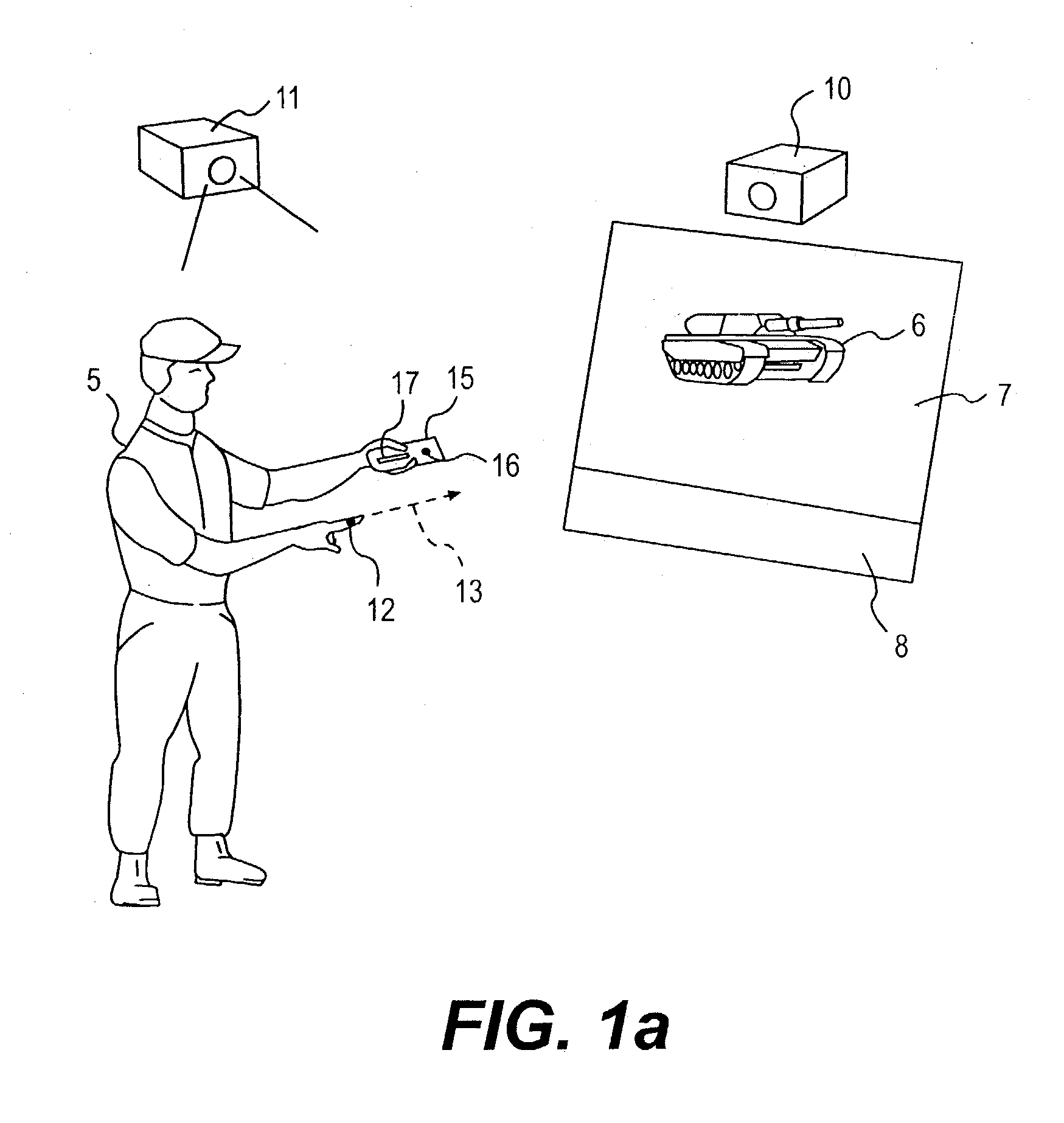
[0091]FIG. 1a illustrates a simple single camera based embodiment of the invention. In this case, a user 5, desires to point at an object 6 represented electronically on the screen 7 and cause the pointing action to register in the software contained in computer 8 with respect to that object (a virtual object), in order to cause a signal to be generated to the display 7 to cause the object to activate or allow it to be moved, (e.g. with a subsequent finger motion or otherwise). He accomplishes this using a single TV camera 10 located typically on top of the screen as shown or alternatively to the side (such as 11) to determine the position of his fingertip 12 in space, and / or the pointing direction of his finger 13.

[0092]It has been proposed by Sigel and others to utilize the natural image of the finger for this purpose and certain US patents address this in the group referenced above. Copending applications by one of the inventors (Tim Pryor) also describe finger related ac...


PUM


Abstract

Affordable methods and apparatus are disclosed for inputting position, attitude (orientation) or other object characteristic data to computers for the purpose of Computer Aided Design, Painting, Medicine, Teaching, Gaming, Toys, Simulations, Aids to the disabled, and internet or other experiences. Preferred embodiments of the invention utilize electro-optical sensors, and particularly TV Cameras, providing optically inputted data from specialized datum's on objects and / or natural features of objects. Objects can be both static and in motion, from which individual datum positions and movements can be derived, also with respect to other objects both fixed and moving. Real-time photogrammetry is preferably used to determine relationships of portions of one or more datums with respect to a plurality of cameras or a single camera processed by a conventional PC.

Description

CROSS REFERENCE TO RELATED APPLICATIONS[0001]This application is a divisional application of Ser. No. 09 / 138,285, filed Aug. 21, 1998 and now U.S. Pat. No. 6,720,949; which application claims benefit of (and hereby incorporates by reference) provisional application Ser. No. 60 / 056,639, filed Aug. 22, 1997, and provisional application Ser. No. 60 / 059,561, filed Sep. 19, 1997.BACKGROUND OF THE INVENTION[0002]1. Field of the Invention[0003]The invention relates to simple input devices for computers, well suited for use with 3-D graphically intensive activities, and operating by optically sensing object or human positions and / or orientations. The invention in many preferred embodiments, uses real time stereo photogrammetry using single or multiple TV cameras whose output is analyzed and used as input to a personal computer.[0004]2. Description of Related Art[0005]The closest known references to the stereo photogrammetric imaging of datum's employed by several preferred embodiments of th...

Claims


Application Information

Patent Timeline
IPC IPC(8): G09G5/08A63F13/02A63F13/06A63F13/219G06F3/00G06F3/01G06F3/038G06F3/042G06T7/00G06T17/40G10H1/00G16H40/67G16H50/50
CPCA63F13/02A63F13/06A63F13/10G06F3/011G06F3/017G06F3/0304G06F3/0325G06F3/0346G06F3/038G06F3/0425G06F3/0428G06F19/3406G06F19/3437G06T7/0042G10H1/0008A63F13/00G01S5/16G06T19/20A63F13/04G06T2219/2021A63F2300/1043A63F2300/1062A63F2300/1075A63F2300/1081A63F2300/1087A63F2300/1093A63F2300/6045A63F2300/69G06F19/3418G10H2220/321G06T2219/2016G06F3/042G06T7/73G16H40/63G16H50/50G16H40/67A63F13/428A63F13/219A63F13/52A63F13/213A63F13/245A63F2300/66
Inventor PRYOR, TIMOTHY R.SMITH, PETER
Owner PRYOR TIMOTHY R
Learn More