
Systems and methods for displaying hazards

a technology of systems and methods, applied in traffic control systems, instruments, and using reradiation, etc., can solve problems such as affecting the safety affecting the processing of updated information, and affecting the safety of the region b>145/b>, so as to reduce the delay in processing updated information and increase the safety of property and personnel results

Active Publication Date: 2006-05-09
L3 TECH INC
View PDF7 Cites 82 Cited by
  • Summary
  • Abstract
  • Description
  • Claims
  • Application Information

AI Technical Summary

Benefits of technology

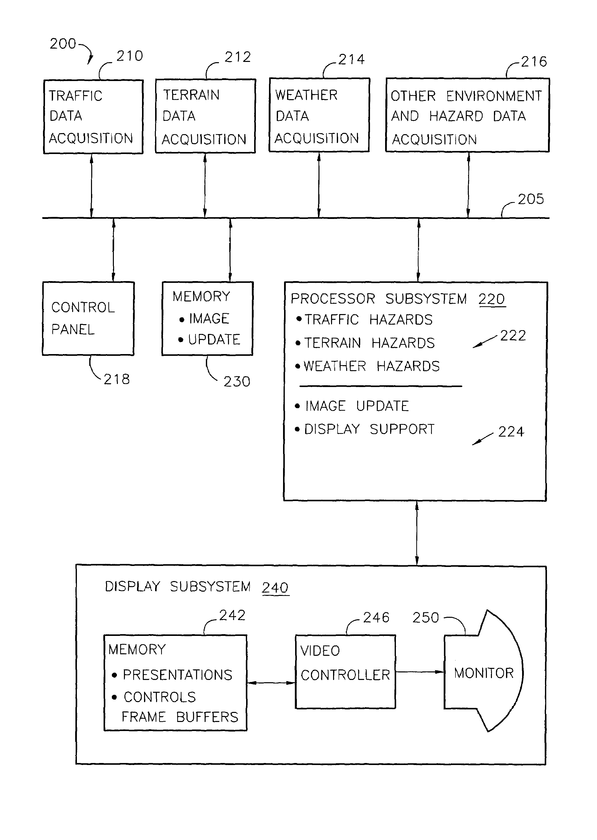
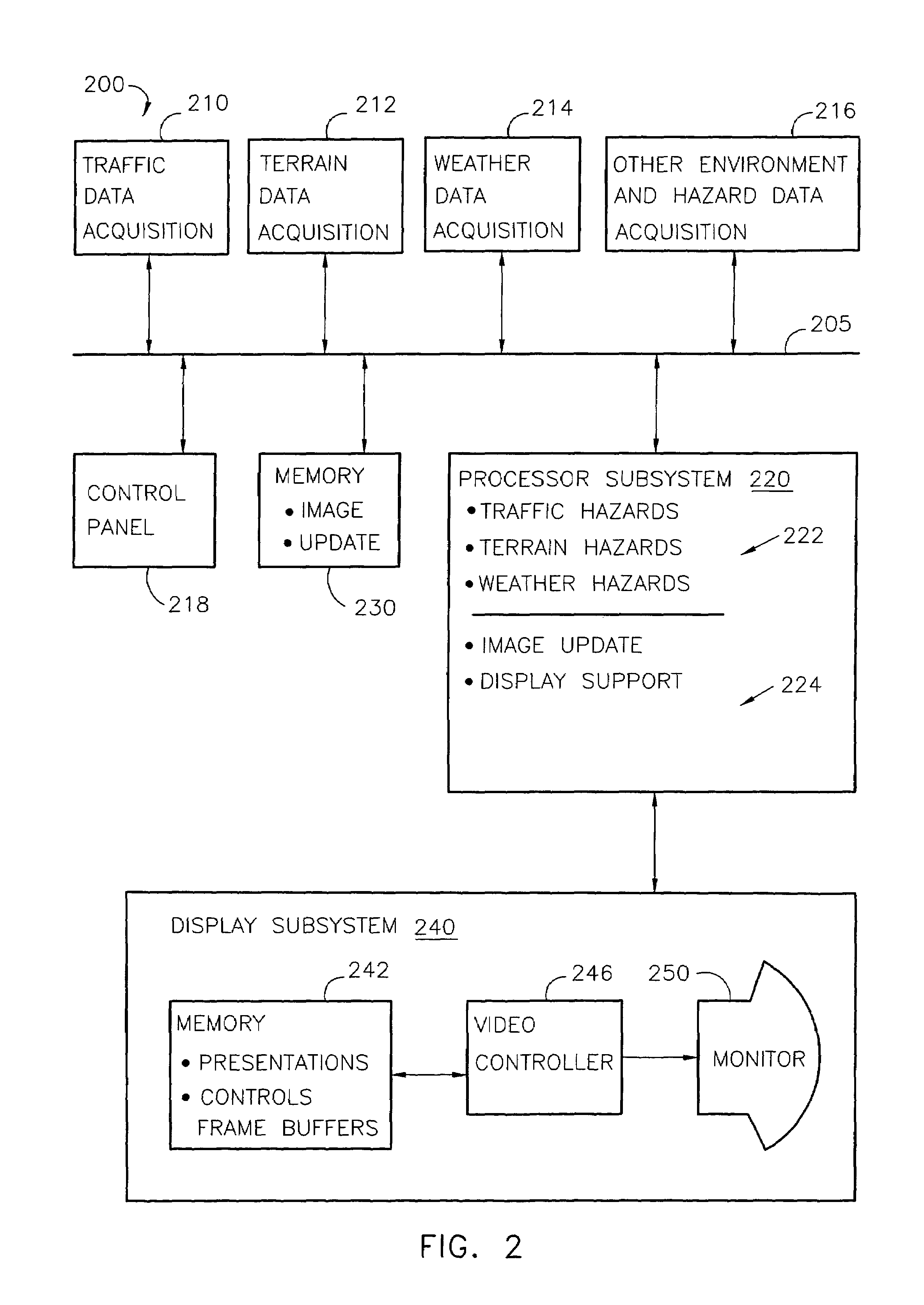
The present invention provides systems and methods for presenting descriptions of hazards to a hazard display. The method includes identifying a first scan mode for processing a first portion of a presentation comprising a hazardous region and identifying a second scan mode for processing a second portion of the presentation not overlapping the first portion. The presentation is then directed in accordance with the first and second scan modes. The system includes a memory device with surveillance data and a processor. The processor updates an image in accordance with the surveillance data to provide an updated image and prepares a presentation in accordance with the updated image. The presentation is then provided to the hazard display. The invention helps to reduce delays in processing updated information, especially with respect to information related to nearby hazards, which increases safety to property and personnel.

Problems solved by technology

Hazards to aircraft include collision with terrain, collision with other aircraft (traffic), and encountering adverse weather.
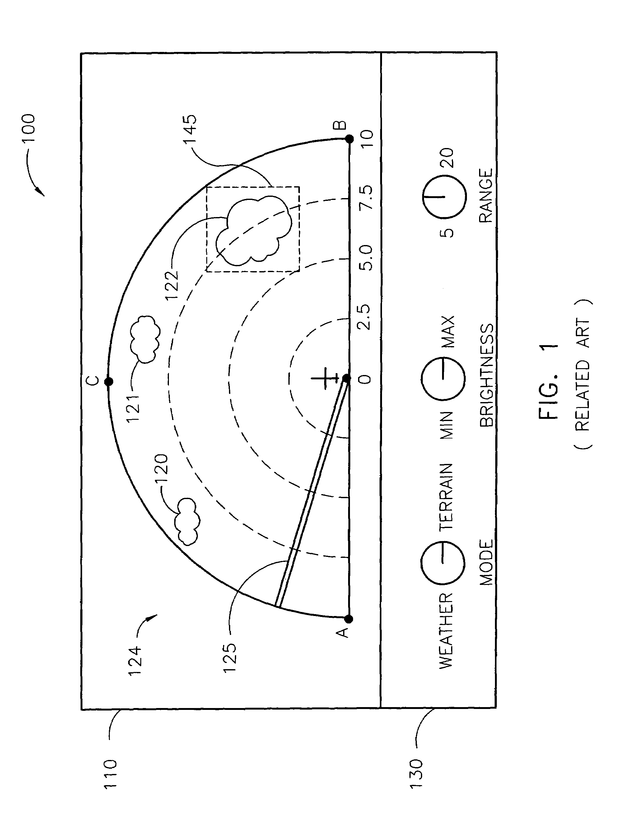
The region 145 may be considered particularly hazardous due to the type, number, or density of individual hazards.
Consequently, it is not possible for an operator to determine a central point (e.g., central azimuth) of a hazard or the perimeter of a hazard until the entire region of the displayed image describing the hazard has been scanned.
Consequently, time may be inappropriately spent updating, at a high resolution, a portion of the displayed image having comparatively little hazard information.
Delay in the presentation of information may delay an operator's awareness of a hazard and may reduce the time the operator has to avoid the hazard

Method used


Image

  • Systems and methods for displaying hazards
  • Systems and methods for displaying hazards
  • Systems and methods for displaying hazards

Examples


Embodiment Construction

[0022]Systems and methods of the present invention reduce delay in the updating, presenting, and / or refreshing of updated information, especially with respect to information related to hazards for presentation on a hazard display. According to the present invention, updating, presenting, and / or refreshing an image is accomplished in a region having hazard information earlier than other regions of the image and with a scan mode different from the scan mode used when fewer or no hazards exist. Consequently, a region of an image having a hazard may be displayed earlier than other regions of the displayed image. According to various aspects of the present invention, a change from a first scan mode to a new scan mode generally includes a difference in one or more of the start position(s) of the new scan, the direction(s) of the new scan, the extent(s) of the new scan, and / or the resolution of the new scan. Plural start positions, directions, and extents apply, for example, to a fan mode....


PUM


Abstract

A system, according to various aspects of the present invention, provides a presentation to a hazard display. The system includes a memory having surveillance data and a processor. The processor updates an image in accordance with the surveillance data to provide an updated image. The processor also prepares a presentation in accordance with the updated image. The processor further provides the presentation to the hazard display. At least one of updating, preparing, and providing utilize a first scan mode for a hazardous region of the presentation and a second scan mode for a nonhazardous region of the presentation.

Description

FIELD OF THE INVENTION[0001]Embodiments of the present invention relate to alerting an operator to hazardous conditions in the environment surrounding the equipment being operated.BACKGROUND OF THE INVENTION[0002]Conventional hazard displays are used to reduce the risk of damage to vehicles, damage to property, personal injury, and loss of life. Such displays are often used by vehicle operators (e.g., aircraft pilots) and operators of supervisory equipment (e.g., air traffic controllers). Hazards to vehicular operation are diverse. Hazards to aircraft include collision with terrain, collision with other aircraft (traffic), and encountering adverse weather. Conventional airborne weather displays and aircraft terrain displays present information describing areas where hazards (also called potential threats) are located relative to the position of the host aircraft. U.S. Pat. No. 4,484,192 to Seitz et al., U.S. Pat. No. 4,825,381 to Bottorf et al., U.S. Pat. No. 5,049,886 to Seitz et a...

Claims


Application Information

Patent Timeline
Patent Type & Authority Patents(United States)
IPC IPC(8): G01S13/95G08G5/00
CPCG08G5/0013G08G5/0091G08G5/0078G08G5/0021
Inventor RIDENOUR, RICHARDSCOTT, STEVEN GREGORY
Owner L3 TECH INC
Learn More