
Methods of and apparatus for controlling polishing surface characteristics for chemical mechanical polishing

Inactive Publication Date: 2006-05-09
APPLIED MATERIALS INC
View PDF21 Cites 5 Cited by
  • Summary
  • Abstract
  • Description
  • Claims
  • Application Information

AI Technical Summary

Benefits of technology

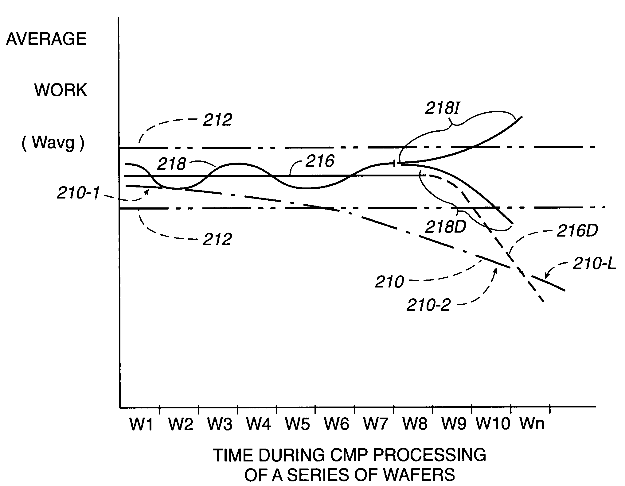
[0009]Broadly speaking, the present invention fills these needs by providing improvements in CMP apparatus and methods by which the use of motor current, and related work performed by such a motor, during CMP operations on a series of wafers are reliable indicators of non-end point aspects of the CMP operations, e.g., aspects other than the structure of the wafer being CMP processed. Such non-end point aspects include, for example, the roughness of a polishing surface that is applied to a series of wafers during ongoing CMP operations. The present invention enables control of a rate of conditioning, e.g., roughening, of the polishing surface in relation to a rate at which the polishing surface becomes smoother during CMP operations performed on such series of wafers.

Problems solved by technology

Without planarization, fabrication of additional metallization layers becomes substantially more difficult due to increased variations in a surface topography of the wafer.
However, in such CMP apparatus having this type of end point detection, the current thus only indicated a change in the structure of the one wafer.
Thus, apparatus for this end point detection was not configured to provide an indication of other aspects of the CMP operation, such as any effects of the CMP process on the CMP apparatus itself.
As a result, motor current has not been relied upon commercially as an indicator of non-end point aspects of CMP operation.

Method used


Image

  • Methods of and apparatus for controlling polishing surface characteristics for chemical mechanical polishing
  • Methods of and apparatus for controlling polishing surface characteristics for chemical mechanical polishing
  • Methods of and apparatus for controlling polishing surface characteristics for chemical mechanical polishing

Examples


Embodiment Construction

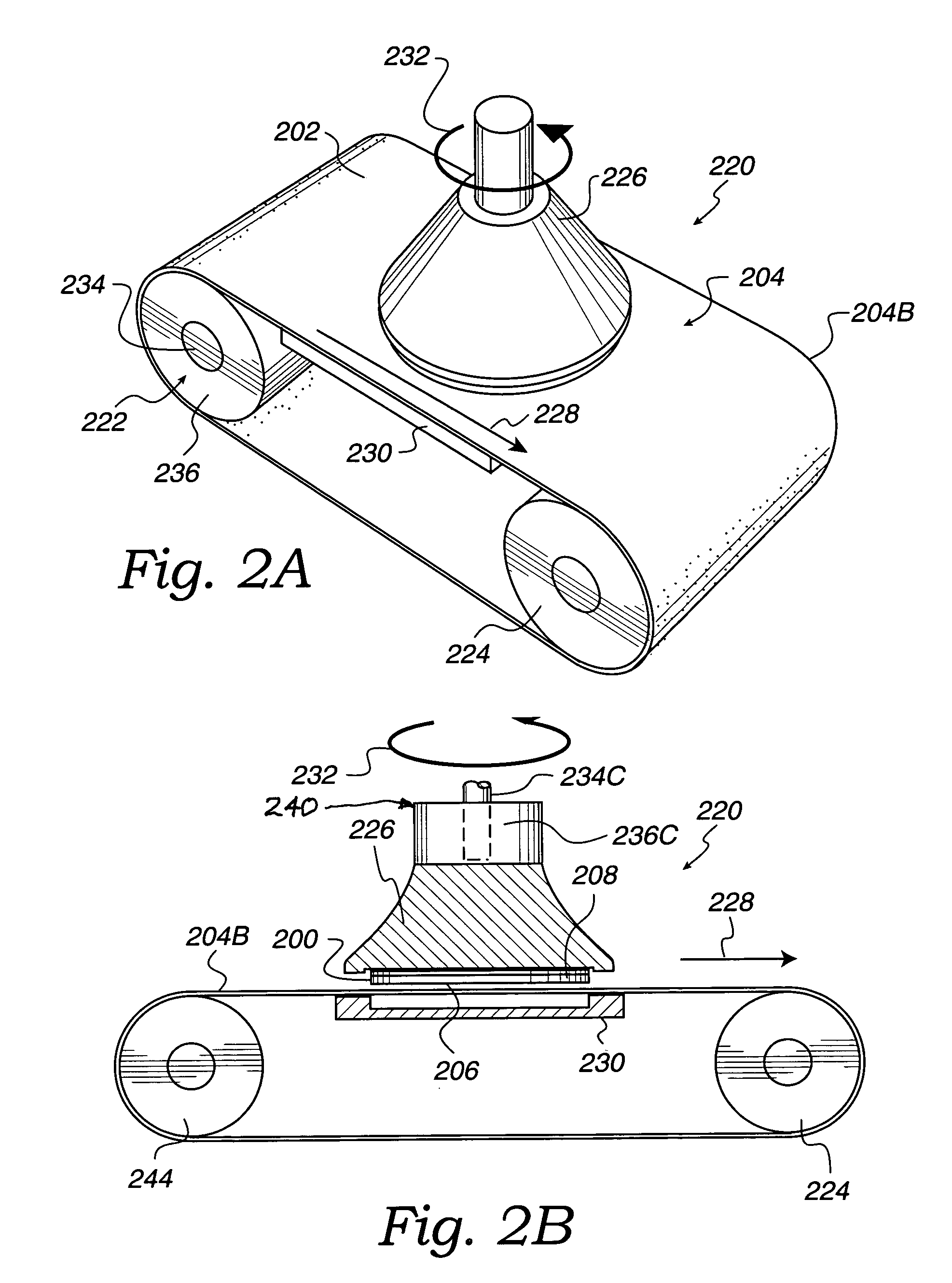
[0030]An invention for a system and method for controlling chemical mechanical polishing operations to provide uniform polishing of wafers is described. In preferred embodiments of the present invention, improvements in CMP apparatus and methods are provided in which motor current, and related work performed by a motor, during CMP operations on a series of wafers are reliable indicators of aspects of CMP operations other than the structure of one wafer that is CMP processed. These aspects include roughness, which is a polishing characteristic of a polishing surface, e.g., of a polishing pad that is applied to the series of wafers during ongoing CMP operations. The improvements enable control of a rate of conditioning of the polishing surface in relation to a rate at which the polishing surface becomes less effective for polishing during CMP operations performed on the series of wafers.

[0031]In the following description, numerous specific details are set forth in order to provide a t...


PUM

PropertyMeasurementUnit
Surfaceaaaaaaaaaa
Velocityaaaaaaaaaa
Surface roughnessaaaaaaaaaa

Abstract

Apparatus and methods control CMP to uniformly polish a series of wafers. Average motor current I(avg) drawn by, and related average work W(avg) performed by, motors during CMP on the wafers reliably indicate quality of a roughness polishing characteristic of a polishing surface of a polishing pad. A conditioner controller controls a rate at which the quality of the polishing surface is restored by conditioning in relation to a rate of change of the quality of the polishing surface due to the CMP. Motor current is measured and averaged over many CMP-processed wafers. The method defines a baseline range of values of average work and controls conditioning according to whether average work is within the baseline range. When the polishing surface moves at constant velocity relative to each of the wafers that are being polished, a control signal based on average motor current represents the quality of the polishing characteristic.

Description

BACKGROUND OF THE INVENTION[0001]1. Field of the Invention[0002]The present invention relates generally to controlling chemical mechanical polishing operations to provide uniform polishing of wafers, and more particularly to controlling a rate of roughening of a polishing surface in relation to a rate at which the polishing surface becomes smoother during chemical mechanical polishing operations performed on a series of wafers.[0003]2. Description of the Related Art[0004]In the fabrication of semiconductor devices, planarization operations are often performed on a semiconductor wafer (“wafer”) to provide polishing, buffing, and cleaning effects. Typically, the wafer includes integrated circuit devices in the form of multi-level structures defined on a silicon substrate. At a substrate level, transistor devices with diffusion regions are formed. In subsequent levels, interconnect metallization lines are patterned and electrically connected to the transistor devices to define a desire...

Claims


Application Information

Patent Timeline
IPC IPC(8): B24B49/18B24B53/00
CPCB24B49/18B24B37/005
Inventor MCCLATCHIE, SIMONNORTON, PETERPHAM, XUYENZHOU, REN
Owner APPLIED MATERIALS INC
Learn More