Vehicle floor tub having a laminated structure

a technology of laminated structure and floor tub, which is applied in the direction of roofs, transportation and packaging, vehicle arrangements, etc., can solve the problems of limited material selection to steel or other metal products, substantial manufacturing challenges, and poor environment for drivers and passengers

Active Publication Date: 2006-05-09
MATERIAL SCIENCES CORPORATION
View PDF11 Cites 23 Cited by
  • Summary
  • Abstract
  • Description
  • Claims
  • Application Information

AI Technical Summary

Benefits of technology

[0013]The viscoelastic layer within the laminated sheet structure provides substantial noise and vibration damping such that the tub body is further characterized by the absence of sound deadening patches or other sound deadeners on the underside of the bottom of the tub body.

Problems solved by technology

In this configuration, the tub must be strong enough to hold approximately 400 lbs. of weight, which limits the material selection to steel or other metal products.
Due to the size of the collapsed seats to be stored in the tubs, substantial manufacturing challenges are presented in forming such a large stamped steel component.
Additionally, the shape of such a tub renders it susceptible to noise radiation which, if untreated, presents undesirably loud cabin noise which creates a poor environment for the driver and passengers.
Disadvantages of mastics include: build variations between vehicles due to manual placement; airborne paint contamination resulting in paint quality issues; labor required for installation; inconsistent melt characteristics; non recyclability; susceptibility to damage during installation; interior packaging limitations due to thickness of mastics; providing only localized damping; and assembly line space requirements.
Disadvantages of this configuration include the additional tooling required to manufacture the doubler, the welding operation required for attachment, interior packaging limitations due to thickness of the doubler, and localized damping only in the area of the doubler panel.
Disadvantages of spray-on deadeners include: masking requirement for spray applications; non-recyclability; process limited by overspray and dripping; robot requirement for application; paint shop contamination; labor on assembly line space requirement; on-going maintenance of robots; and only localized dampening coverage.
Disadvantages of fiberglass matting include labor and assembly space requirements; fastener requirements; interior packaging limitations due to thickness; and the added expense and weight of the fiberglass parts.

Method used


Image

  • Vehicle floor tub having a laminated structure
  • Vehicle floor tub having a laminated structure
  • Vehicle floor tub having a laminated structure

Examples


Embodiment Construction

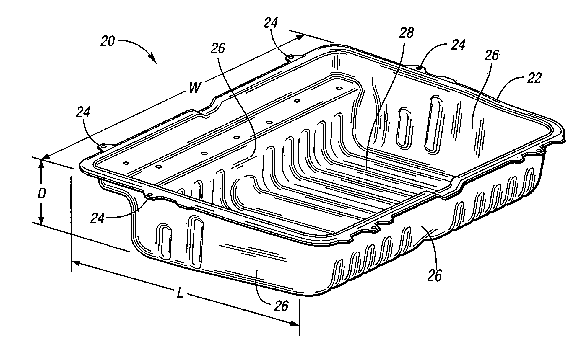
[0020]The present invention provides a tub which is used to store a collapsed vehicle seat beneath the floor a vehicle, as described, by way of example, in the above referenced U.S. Patent Application Publication 2004 / 0100116. The tub described herein maybe used in connection with the structure described in the above referenced U.S. Patent Publication (i.e. it would replace the tub 34 identified in the above referenced publication).

[0021]Specifically, the tub of the present invention is cold formed from a laminated sheet structure (a.k.a. constrained layer viscoelastic material) 10, as illustrated schematically in FIG. 1. This laminated sheet structure is available under the product name Quiet Steel® from Material Sciences Corporation of Farmington Hills, Mich. The laminated sheet structure 10 includes first and second cold rolled sheets of steel 12, 14 having an engineered viscoelastic layer 16 therebetween spanning the entirety of both steel sheets 12, 14. The laminated steel shee...


PUM


Abstract

A tub is configured for attachment to a vehicle floor to receive a collapsed vehicle seat therein. The tub is formed from a laminated sheet structure including two layers of cold rolled steel having a viscoelastic layer therebetween spanning the entirety of both steel layers. The tub body has a rim, side walls extending downward from the rim, and a bottom supported by the side walls. The tub body is approximately 10″ deep from the rim to the bottom. The laminated sheet structure has a bending rigidity between approximately 9.7 and 16.5 Nm to enable the forming of the side walls.

Description

TECHNICAL FIELD[0001]The present invention relates to the vehicle floor tub including a laminated steel structure with a viscoelastic layer for sound deadening, where in the laminated structure has a desired bending rigidity to enhance manufacturability.BACKGROUND OF THE INVENTION[0002]Various prior art patents describe storage spaces that are provided beneath the vehicle floor. One example of a vehicle having a rear cargo space beneath the floor is described in U.S. Pat. No. 3,325,207. This patent describes a hidden cargo storage area which is designed into the body of the vehicle and is provided with a pivoting floor section which covers the hidden cargo storage area. The hidden cargo storage area is designed to accommodate a wheel and other cargo.[0003]Similarly, U.S. Pat. No. 5,257,846 discloses a luggage space which is located behind a rear seat of a station wagon type vehicle.[0004]U.S. Patent Application Publication 2004 / 0100116, to Rhodes et al, published May 27, 2004, and h...

Claims


Application Information

Patent Timeline
Patent Type & Authority Patents(United States)
IPC IPC(8): B60R27/00B60R99/00
CPCB62D29/001B62D25/20
Inventor JACOBS, JON E.SCHWAEGLER, JAMES R.
Owner MATERIAL SCIENCES CORPORATION
Why Eureka
Try Eureka