Implant for altering the iris color and method of locating and fixing an implant for altering the iris color
- Summary
- Abstract
- Description
- Claims
- Application Information
AI Technical Summary
Benefits of technology
Problems solved by technology
Method used
Image
Examples
first embodiment
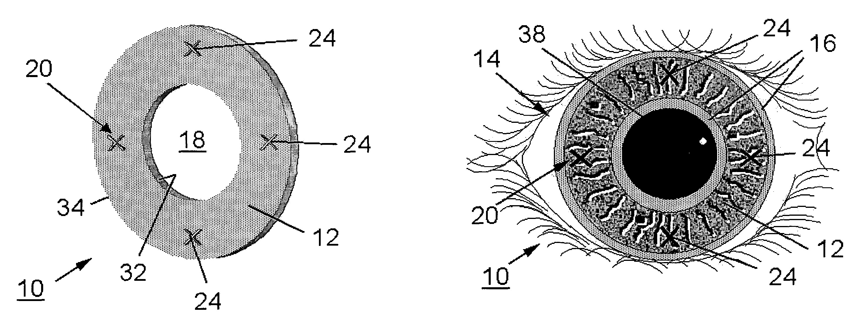
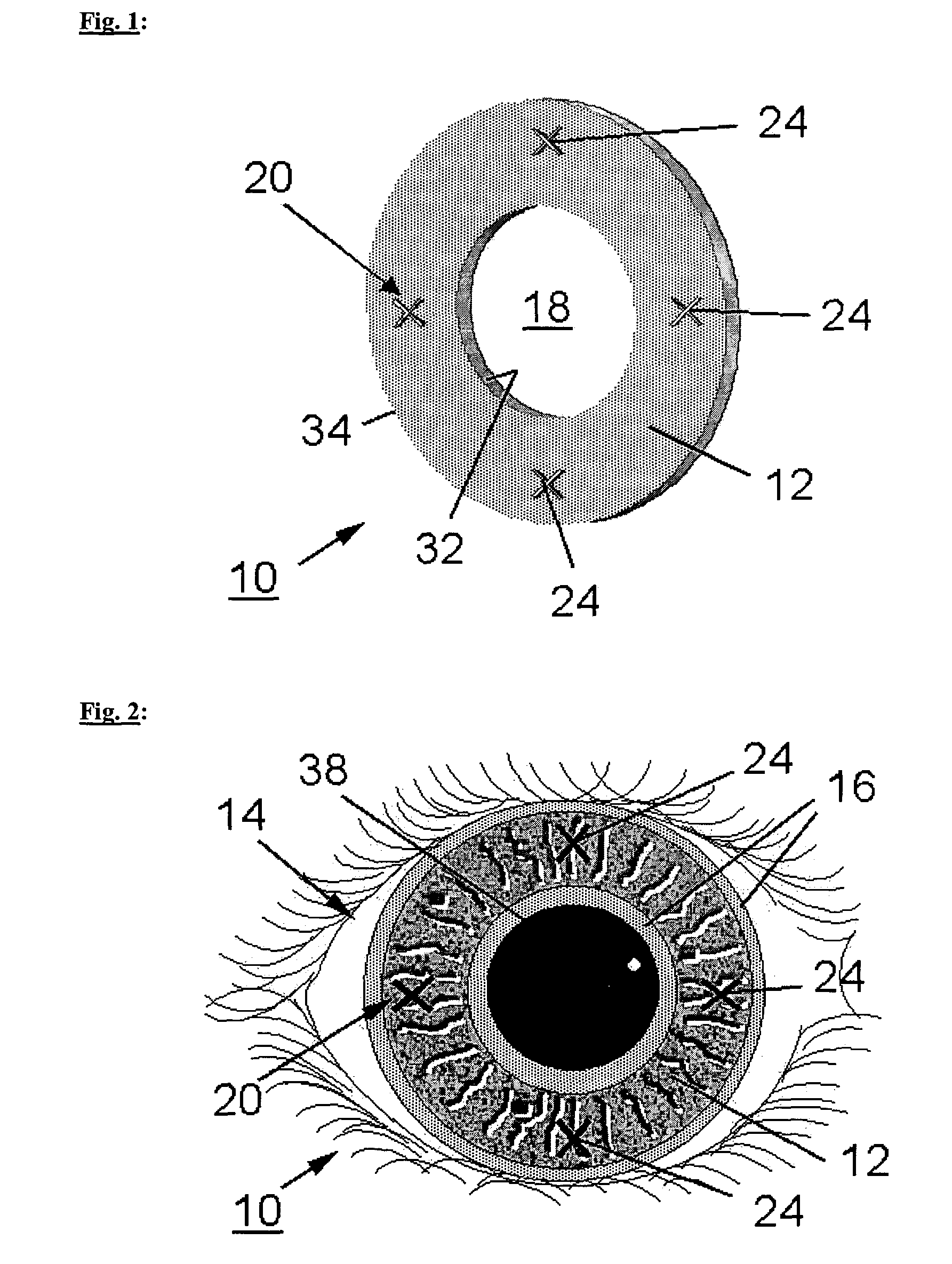
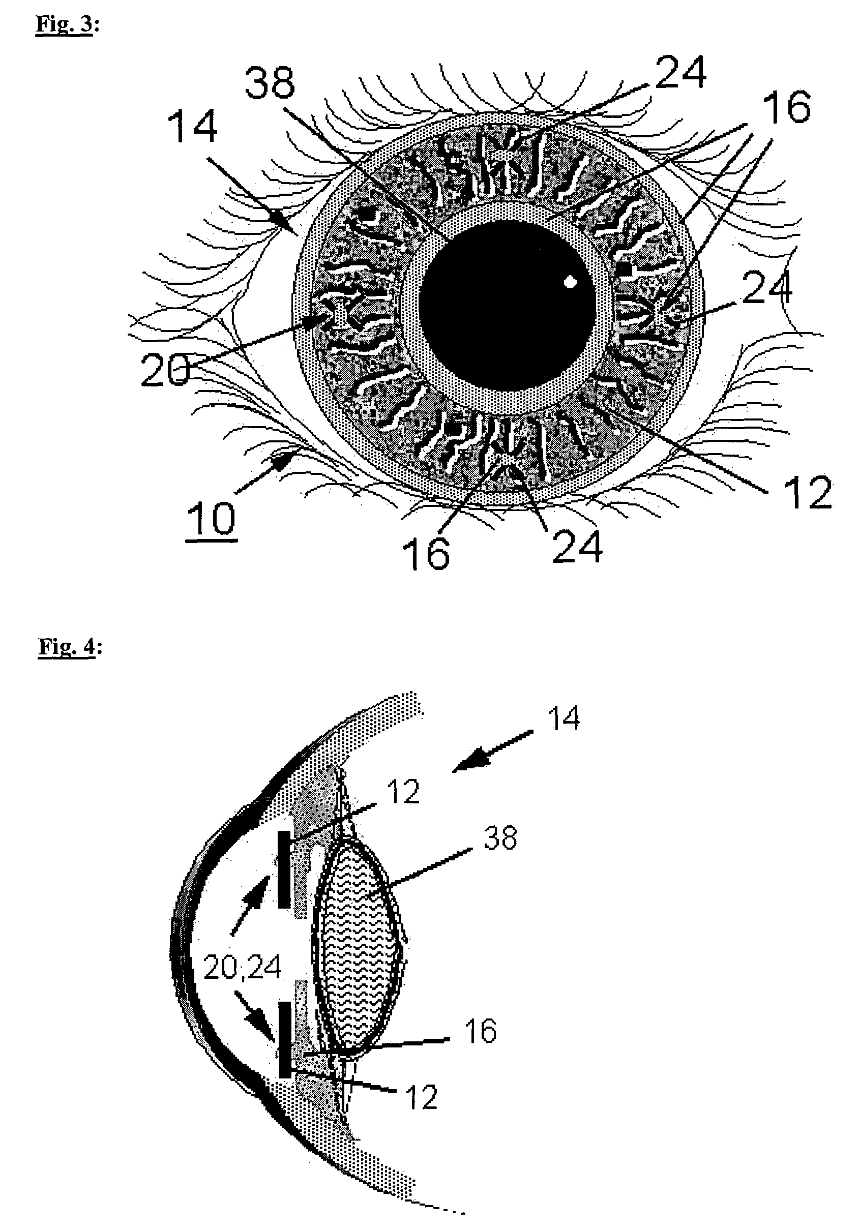
[0031]FIG. 1 shows in a schematic representation an implant 10 for altering the iris color according to a One recognizes that the implant 10 is formed annularly and has an annular area 12, which comes to rest on the iris 16 of an eye 14 (cf. FIG. 2). Additionally, a central circular opening 18 is formed in the implant, which comes to rest in the region of a pupil 38 of the eye 14 (cf. FIG. 2) after disposing the implant 10 on the iris 16.
[0032]Further, one recognizes in the illustrated first embodiment of the implant 10, that within the annular area 12 several attaching means 20 are disposed. Therein, the attaching means 20 each consist of an opening 24 extending through the annular area 12. Therein, the openings 24 serve for passing and anchoring the underlying partial areas of the iris 16. In the illustrated embodiment, the openings 24 are formed in the shape of cross-slits. However, every other shape of the openings 24 is also conceivable. Further, the openings 24 can have protr...
second embodiment
[0040]Also the implant 10 according to the illustrated second embodiment has circular edges 32, 34 and thus forms a ring. Therein, the central opening 18 of the ring serves for light transmission.
[0041]FIG. 6 shows a representation of the implant 10 according to FIG. 5, wherein the implant 10 rests on the iris 16. One recognizes also in this embodiment, that the attaching means 22, 26 are formed within the annular area 12 of the implant 10. Thus, the attaching means 22, 26 come to rest exclusively on the iris 16.
[0042]By the sectional view of the implant 10 according to the FIGS. 5 and 6, shown in FIG. 7, it is appreciable, how the implant 10 rests on the iris 16 and is attached thereto. One recognizes that the attaching means 22, 26 engage with the underlying partial areas of the iris 16. Therein, the hook-like protrusions 26 point toward the ring inner side of the implant 10. The central opening 18 surrounded by the annular area 12 allows for the unimpeded light transmission throu...
third embodiment
[0043]FIG. 8 shows a schematic view of an implant 10 according to a One recognizes that the edges 32, 34 of the implant are formed serrated. However, as a whole, the implant 10 is further formed annularly, i.e. the implant 10 again has an annular area 12 and a central opening 18. It is also possible that the edges 32, 34 of the implant 10 have another shape.
PUM
 Abstract
Description
Claims
Application Information
 - R&D
- Intellectual Property
- Life Sciences
- Materials
- Tech Scout
- Unparalleled Data Quality
- Higher Quality Content
- 60% Fewer Hallucinations
Browse by: Latest US Patents, China's latest patents, Technical Efficacy Thesaurus, Application Domain, Technology Topic, Popular Technical Reports.
© 2025 PatSnap. All rights reserved.Legal|Privacy policy|Modern Slavery Act Transparency Statement|Sitemap|About US| Contact US: help@patsnap.com


