
Neurovascular stent and method

a stent and neurovascular technology, applied in the field of neurovascular stents and methods, can solve the problems of not meeting the requirements of several requirements outlined above, affecting the treatment of patients, and requiring several formidable challenges

Inactive Publication Date: 2006-05-02
STRYKER EURO OPERATIONS HLDG LLC +1
View PDF41 Cites 193 Cited by
  • Summary
  • Abstract
  • Description
  • Claims
  • Application Information

AI Technical Summary

Benefits of technology

[0009]The invention includes, in one aspect, a stent designed for catheter delivery to a target neurovascular site via a tortuous path in a contracted state, and deployment at the target site in an expanded state. The stent includes a plurality of expandable tubular members, where each member is composed of a continuous wire element forming a plurality of wave segments, and each segment contains a pair of opposite looped peaks and has a wave shape such that the distance between adjacent sides of a wave in the stent's expanded state, on proceeding from a peak toward opposite peaks, increases monotonically with an inflection point therebetween. Adjacent tubular members are connected by axial connectors, preferably joining adjacent peaks of adjacent members, and preferably spaced from one another by intervening, unconnected confronting peaks. Radial expansion of the stent from a contracted to expanded state is accommodated by movement of adjacent wave-segment peaks away from one another, without significant change in the axial dimension of the stent.

Problems solved by technology

The disease is devastating, often affecting healthy people in their 40's and 50's, with about half of the rupture victims succumbing within a month, and with half of the survivors becoming seriously disabled as a result of the initial hemorrhage or of a delayed complication.
Such a treatment, however, involves several formidable challenges.
Although a variety of intravascular stents have been proposed heretofore, for example, in U.S. Pat. Nos. 4,512,338, 4,503,569, 4,553,545, 4,795,485, 4,820,298, 5,067,957, 5,551,954, 5,562,641, and 5,824,053, none of these structures adequately meets the several requirements outlined above.
In particular, the problem of providing a stent skeletal structure that has a contracted state diameter of 0.5-2 mm, is highly flexible in a contracted state, has a high expansion ratio on delivery from a catheter, and resists metal fatigue on expanding and contracting, has not been adequately solved heretofore.

Method used


Image

  • Neurovascular stent and method
  • Neurovascular stent and method
  • Neurovascular stent and method

Examples


Embodiment Construction

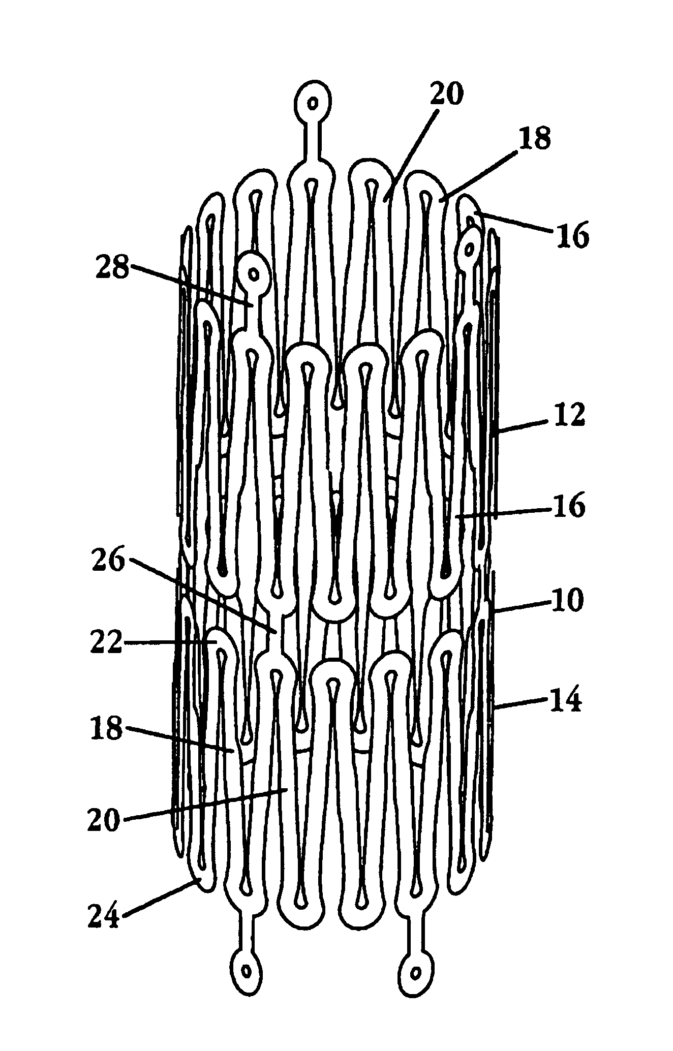
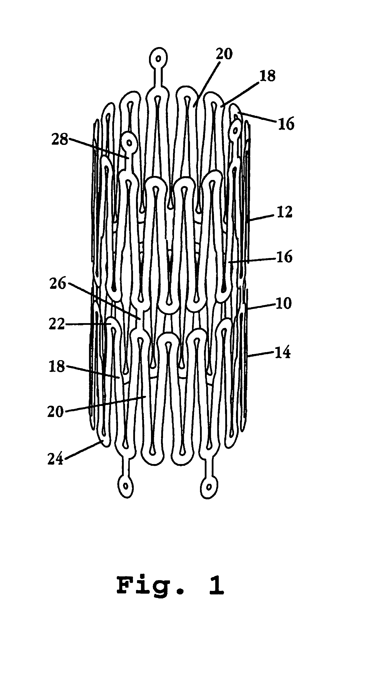
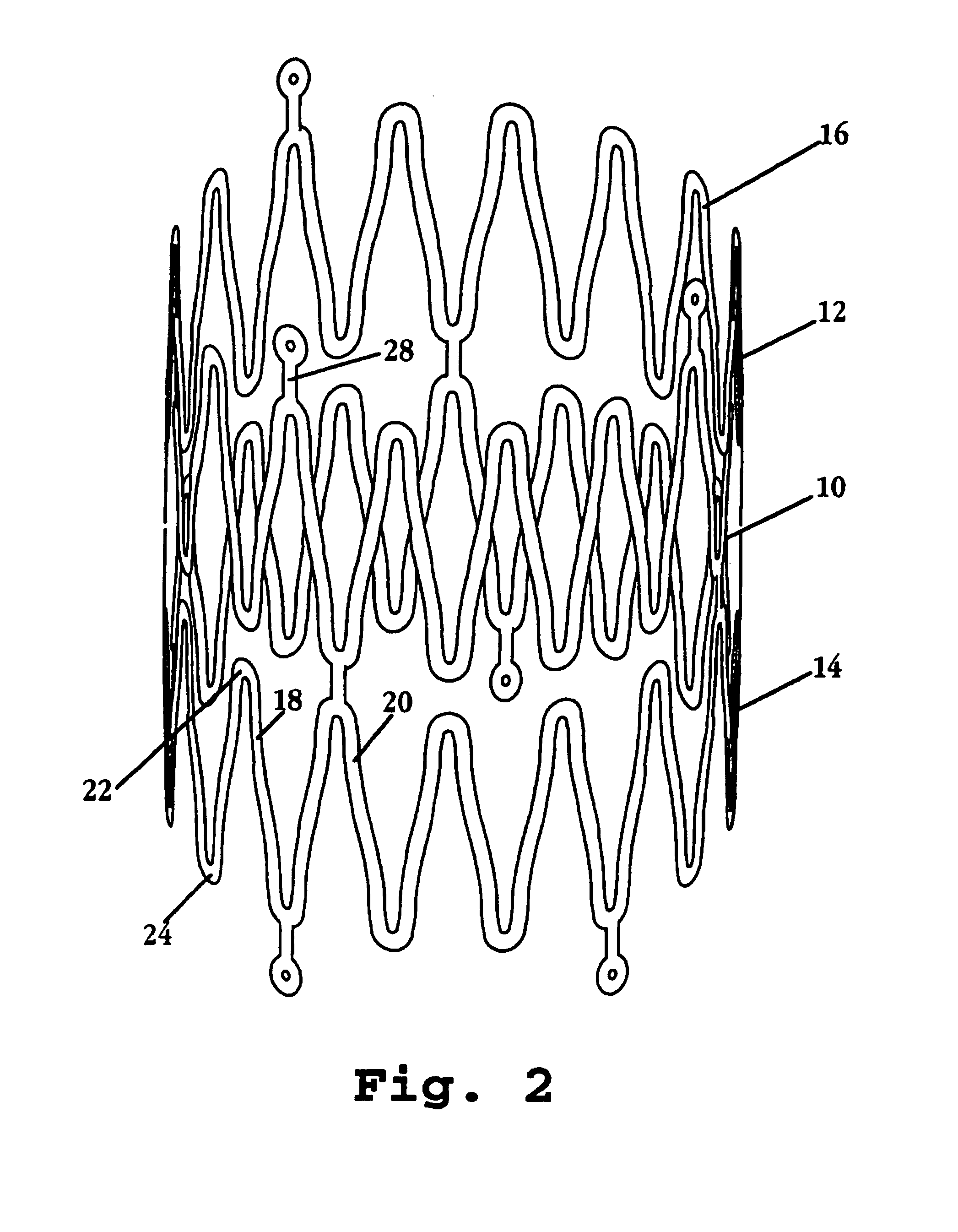
[0022]FIGS. 1 and 2 show a portion of a stent 10 constructed in accordance with the invention, in the stent's contracted and expanded states, respectively. The stent includes a plurality of expandable tubular members, such as tubular members 12, 14. In actual construction, the stent may include many such members, e.g., 2-20, collectively forming an elongate cylindrical tube.

[0023]Each member of the stent is formed of a continuous wire element, such as wire element 16 in member 12, forming a plurality of wave segments, such as wave segments 18, 20 in member 14, whose shape and expansion characteristics will be described further below with respect to FIGS. 3-5. The wave segments have opposite looped peaks, such as looped peaks 22, 24 in wave segment 18.

[0024]Adjacent tubular members are connected one to another by axial connectors, such as axial connector 26 joining members 14, 16, and axial connector 28 joining tubular member 12 to a third member (not shown). As seen, the axial conne...


PUM


Abstract

A stent designed for catheter delivery to a target neurovascular site via a tortuous path, in a contracted state, and deployment at the target site, in an expanded state, is disclosed. The stent includes a plurality of expandable tubular members, where member is composed of a continuous wire element forming a plurality of wave segments, and segment contains a pair of opposite looped peaks having a wave shape such that the distance between adjacent sides of a wave, on proceeding from a peak toward opposite peaks, increases monotonically with an inflection point therebetween. The expandable tubular members are joined through adjacent peaks by axial connectors Radial expansion of the stent from a contracted to expanded state is accommodated by movement of adjacent wave-segment peaks away from one another, without significant change in the axial dimension of the stent. Also disclosed are a system incorporating the stent, and a method of treating a neurovascular abnormality.

Description

[0001]This application claims priority of U.S. Provisional Patent Application Ser. No. 60 / 241,101 filed on Oct. 16, 2000, expressly incorporated in its entirety herein by reference.FIELD OF THE INVENTION[0002]The present invention relates to a vascular endoprosthesis, such as a stent, for placement in an area of a body lumen that has been weakened by damage or disease such as by aneurysm, and in particular, to a stent adapted for placement at a neurovascular site, and to a method of using the stent in treating a neurovascular aneurysm.BACKGROUND OF THE INVENTION[0003]Rupture of non-occlusive cerebrovascular lesions, such as intracranial saccular aneurysms or arterio-venous fistulae, is a major cause of stroke. Rupture of an aneurysm causes subarachnoid hemorrhage in which blood from a ruptured vessel spreads over the surface of the brain. About 2.5% of the United States population (4 million Americans) have an unruptured aneurysm. About 100,000 of these people suffer a subarachnoid ...

Claims


Application Information

Patent Timeline
Patent Type & Authority Patents(United States)
IPC IPC(8): A61F2/06A61F2/82
CPCA61F2/91A61F2/915A61F2/95A61F2/966A61F2230/0054A61F2002/823A61F2002/91541A61F2002/91558
Inventor RIVELLI, JR., PATRICKPIPLANI, ALECDONAHUE, SEANLEYNOV, ALEXANDER
Owner STRYKER EURO OPERATIONS HLDG LLC
Learn More