
Cleaning system

a cleaning system and cleaning technology, applied in the field of cleaning systems, can solve the problems of large maintenance and repair downtime, complex design, and easy malfunction, and achieve the effect of easy and cost-effective way

Inactive Publication Date: 2006-05-02
HYDROBALL TECHNICS HLDG PTE LTD
View PDF15 Cites 9 Cited by
  • Summary
  • Abstract
  • Description
  • Claims
  • Application Information

AI Technical Summary

Benefits of technology

[0031]An advantage of the described embodiment of the invention is that the different pressures at the inlet pipe and the outlet pipe create suction force which provides an easy and cost efficient way of circulating the cleaning balls for cleaning the tubing. Such a system is also environmental friendly since there is no wastage of the fluid.

Problems solved by technology

However, a disadvantage of using a pump to recirculate the balls is that the pump is susceptible to malfunctioning and such a system usually requires considerable downtime for maintenance and repair.
A disadvantage of this prior art is the complexity of the design which requires a sequence of actions to close and open the plurality of valves to recirculate the balls.
As a result, the fluid is wasted each time the balls are recirculated and the cost of maintaining such a system may be relatively expensive.

Method used


Image

  • Cleaning system
  • Cleaning system
  • Cleaning system

Examples


Embodiment Construction

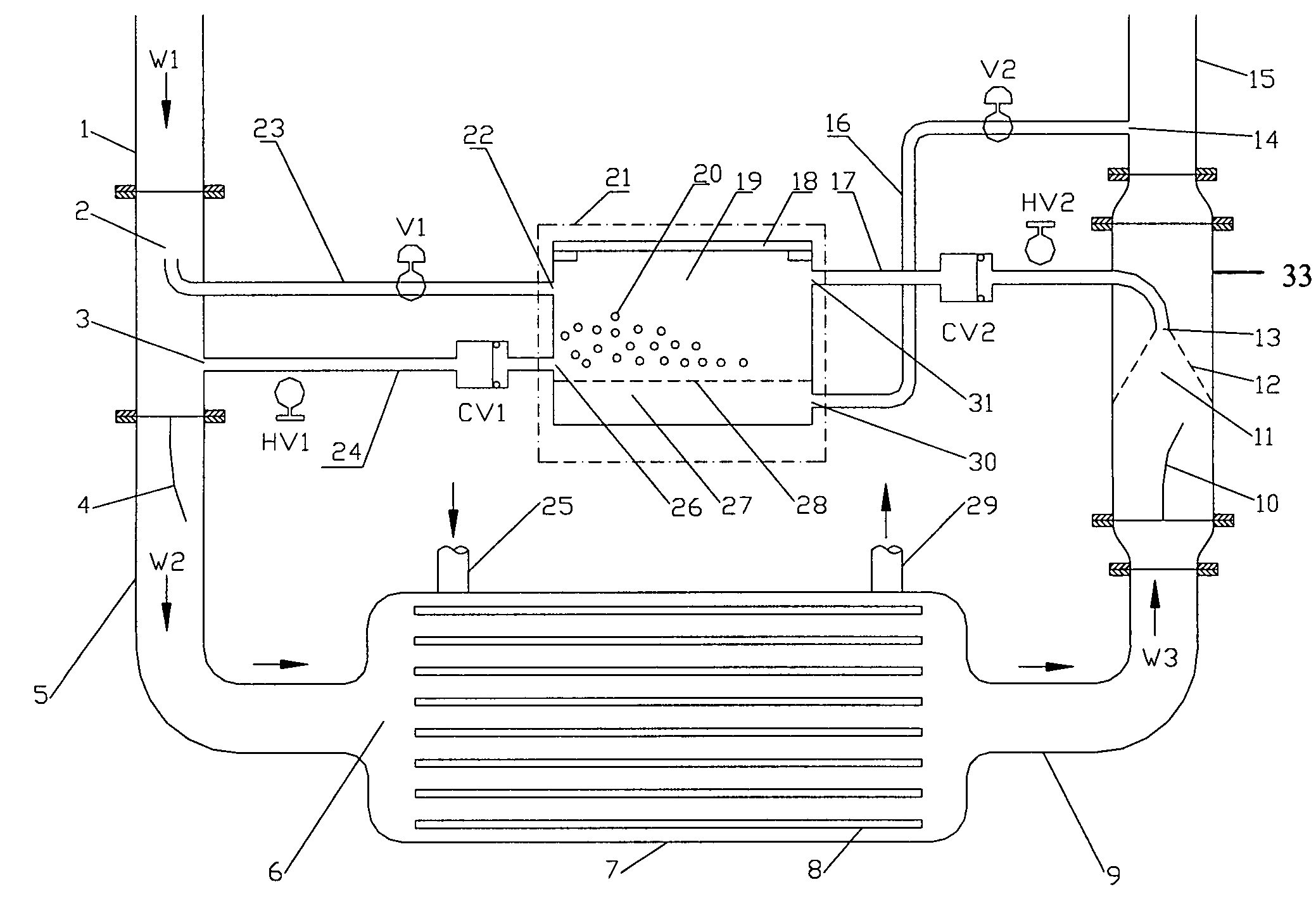
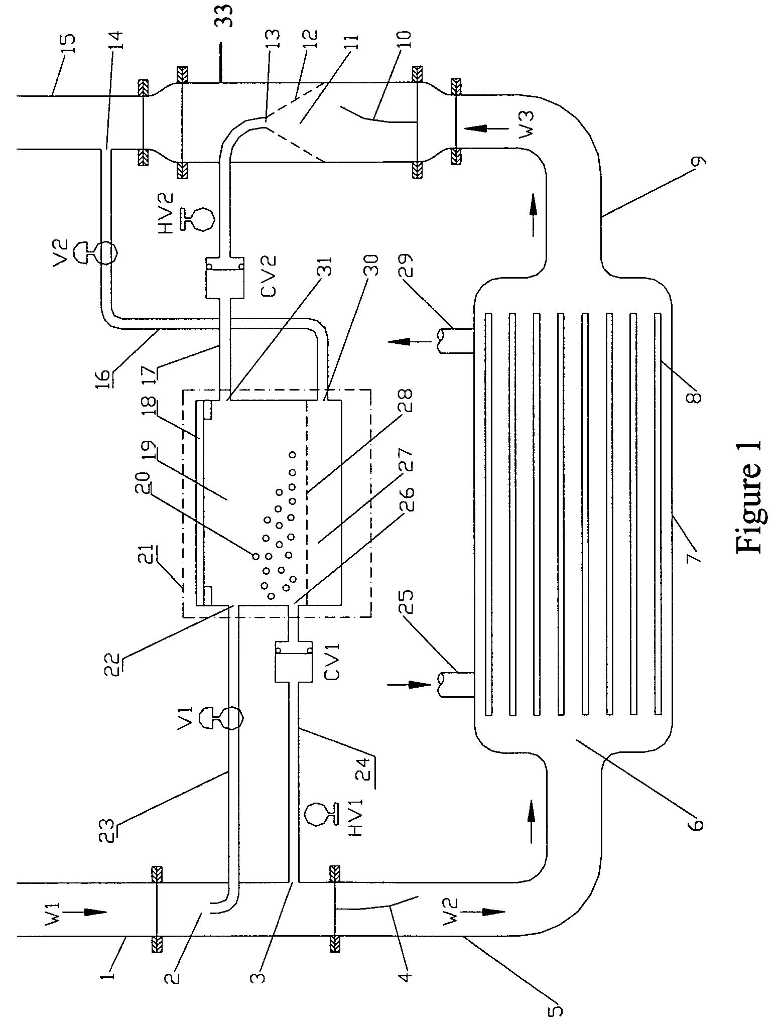
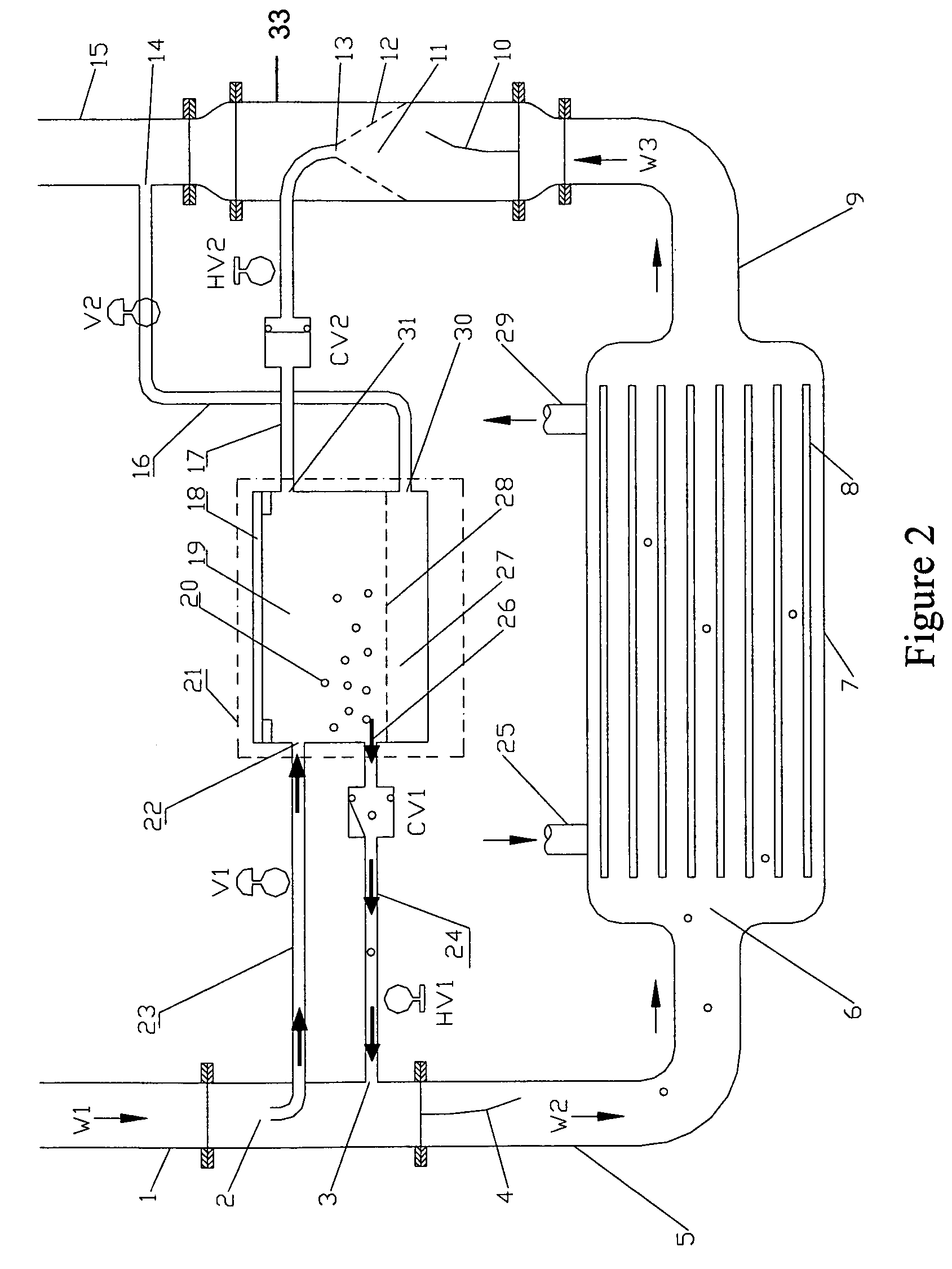
[0040]FIG. 1 illustrates a cleaning system used to clean tubing 8 in a condenser 7. The tubing 8 is in the form of a plurality of parallel spaced tubes which are connected to an inlet pipe 5 and an outlet pipe 9. A cooling fluid such as water is passed through the tubing 8 in order to condense another fluid, such as steam or a refrigerant gas, from an inlet 25 which circulates through the spaces between the tubing 8 and to an outlet 29.

[0041]The cooling fluid (in a direction as indicated by W1) is circulated through the condenser tubing 8 from an inlet duct 1, which is connected to the upstream side of the condenser tubing 8 by the inlet pipe 5, to an outlet duct 15 connected to the downstream side of the tubing 8 by the outlet pipe 9.

[0042]The cleaning system comprises a plurality of cleaning elements and in this embodiment cleaning balls 20 are used. Such cleaning balls 20 are typically made from spongy material and have a diameter slightly larger than the diameter of the tubing 8...


PUM


Abstract

A cleaning system for cleaning tubing using cleaning balls (20) circulated with the fluid through tubing (8). The system includes a separator (12) having a perforated funnel, which permits the fluid, but not the cleaning balls (20), to pass through. A housing (21) having an apertured partition (28) is used to divide the housing (21) into an first compartment (19) and a second compartment (27). An entrance (2) of a fluid supply pipe (23) and an exit (3) of a ball supply pipe (24) are formed for creating a difference in pressure to create a suction force to recirculate the cleaning balls (20) from the housing (21) via the ball supply pipe (24), back to the tubing (8) for cleaning the walls of the tubing (8). An entrance (13) of a ball return pipe (17) and an exit (14) of a fluid return pipe (16) are formed for creating a difference in pressure to create a suction force to recirculate the cleaning balls (20) from the separator (12) via the ball return pipe (17), into the housing (21).

Description

CROSS-REFERENCE TO RELATED APPLICATIONS[0001]This application is the National Stage of International Application No. PCT / SG03 / 00065, filed Mar. 28, 2003, which claims the benefit of Singapore Application Nos. SG 200203246-4, filed May 30, 2002, and SG 200205422-9, filed Sep. 9, 2002, the contents of which are incorporated by reference herein.FIELD OF THE INVENTION[0002]This invention relates to a cleaning system which uses mobile cleaning elements for cleaning the inside of tubing.BACKGROUND OF THE INVENTION[0003]A heat distributing system typically has a condenser unit which includes tubing to conduct fluids. There have been proposed different ways of cleaning the inside of such tubing to prevent the build up of dirt or other unwanted deposits Inside the tubing as the fluids travel through the tubing.[0004]One proposed way is the use of cleaning balls made of rubber or spongy material which have a diameter slightly larger than the tubing so that when they travel through the tubing ...

Claims


Application Information

Patent Timeline
Patent Type & Authority Patents(United States)
IPC IPC(8): F28G1/00B08B9/04F28G1/12
CPCB08B9/055F28G1/12B08B9/0552
Inventor SOH, BENG KIAT PETER
Owner HYDROBALL TECHNICS HLDG PTE LTD
Learn More