
Drive device of the bull-wheel of a single carrying-hauling rope chair lift with fixed rope grips

a technology of bull-wheel and lift, which is applied in the direction of transportation and packaging, train hauling devices, rope railways, etc., can solve the problems of increasing the number of operating personnel required, the cost of these known installations, and the complexity of such a kinematic transmission system, so as to reduce the length of the space occupied, the structure is simplified

Active Publication Date: 2006-05-02
POMAGALSKI SA
View PDF12 Cites 7 Cited by
  • Summary
  • Abstract
  • Description
  • Claims
  • Application Information

AI Technical Summary

Benefits of technology

The invention is a fixed single carrying-hauling rope chair lift that uses a maximum number of standard mechanical components and reduces the space occupation of the terminal. The geared motor mechanism is composed of an electric motor and a mechanical speed reducer, which results in a short kinematic system without requiring intermediate transmission means. The hub of the bull-wheel rotates around the sheath with interposed bearings and a drive sleeve connected to the second rotary shaft of the speed reducer. The mechanical speed reducer with gearing-down cog-wheels is situated above the bull-wheel and opposite from the electric motor. The bull-wheel is equipped with a toothed wheel designed to cooperate with an emergency motor securedly attached to the carriage. The support device comprises a base supporting fixed horizontal sections along which the carriage moves by means of roller means. The support carriage of the bull-wheel is associated with a tensioning device acting in the direction of the line to mechanically tension the rope. The invention achieves a simplified structure and reduced space occupation, regardless of whether a bull-wheel or a tensioning pulley is used.

Problems solved by technology

Implementation of such a kinematic transmission system is complicated and occupies a large longitudinal space in the terminal.
The diversity of the sub-assemblies and the equipment assembly and adjustment time increase the number of operating personnel required and the cost of these known installations.

Method used


Image

  • Drive device of the bull-wheel of a single carrying-hauling rope chair lift with fixed rope grips
  • Drive device of the bull-wheel of a single carrying-hauling rope chair lift with fixed rope grips
  • Drive device of the bull-wheel of a single carrying-hauling rope chair lift with fixed rope grips

Examples


Embodiment Construction

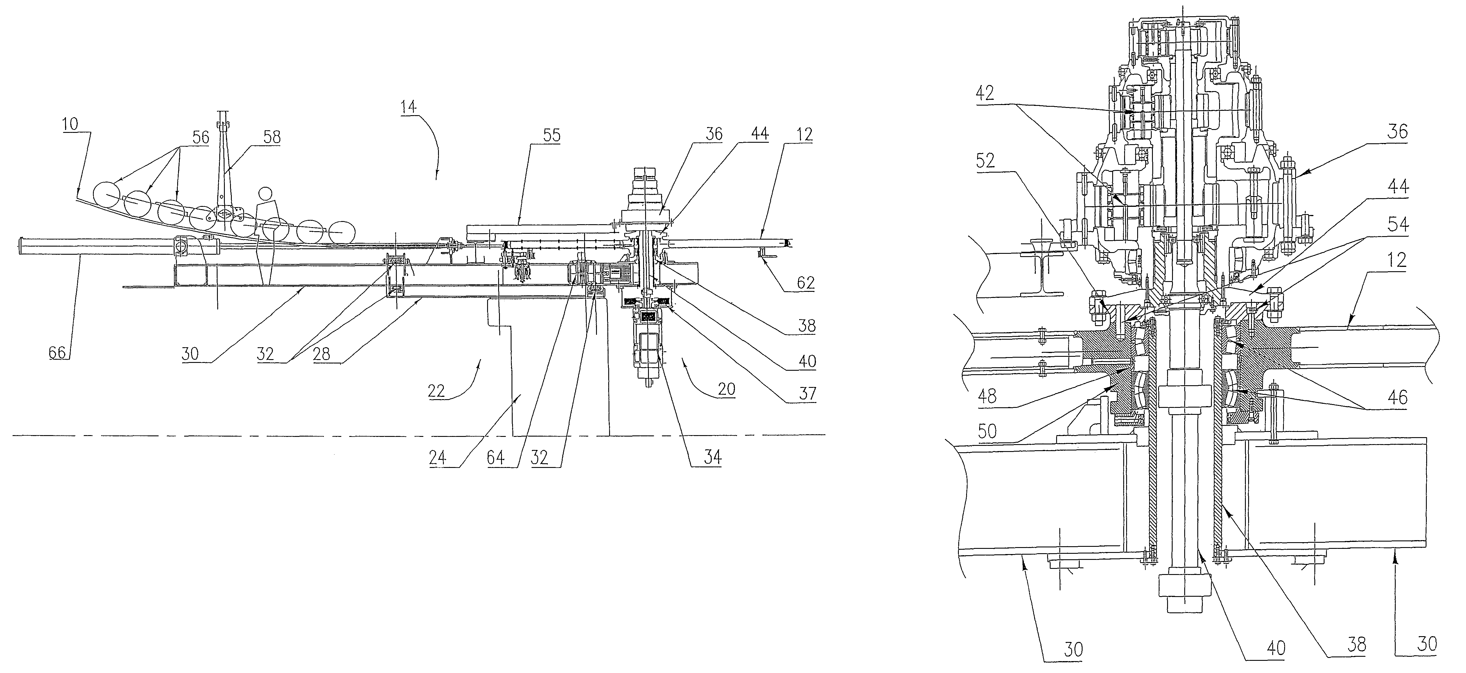
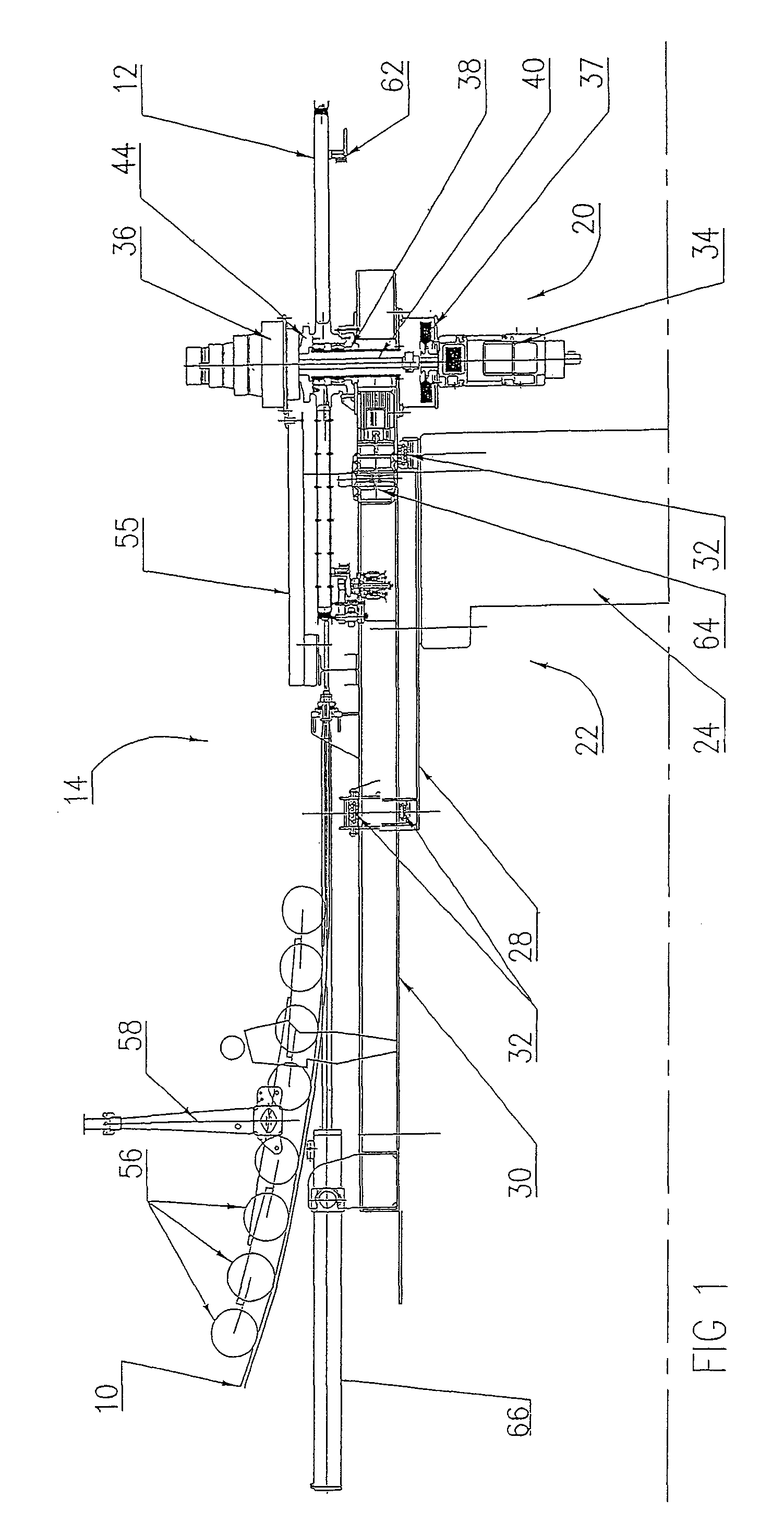
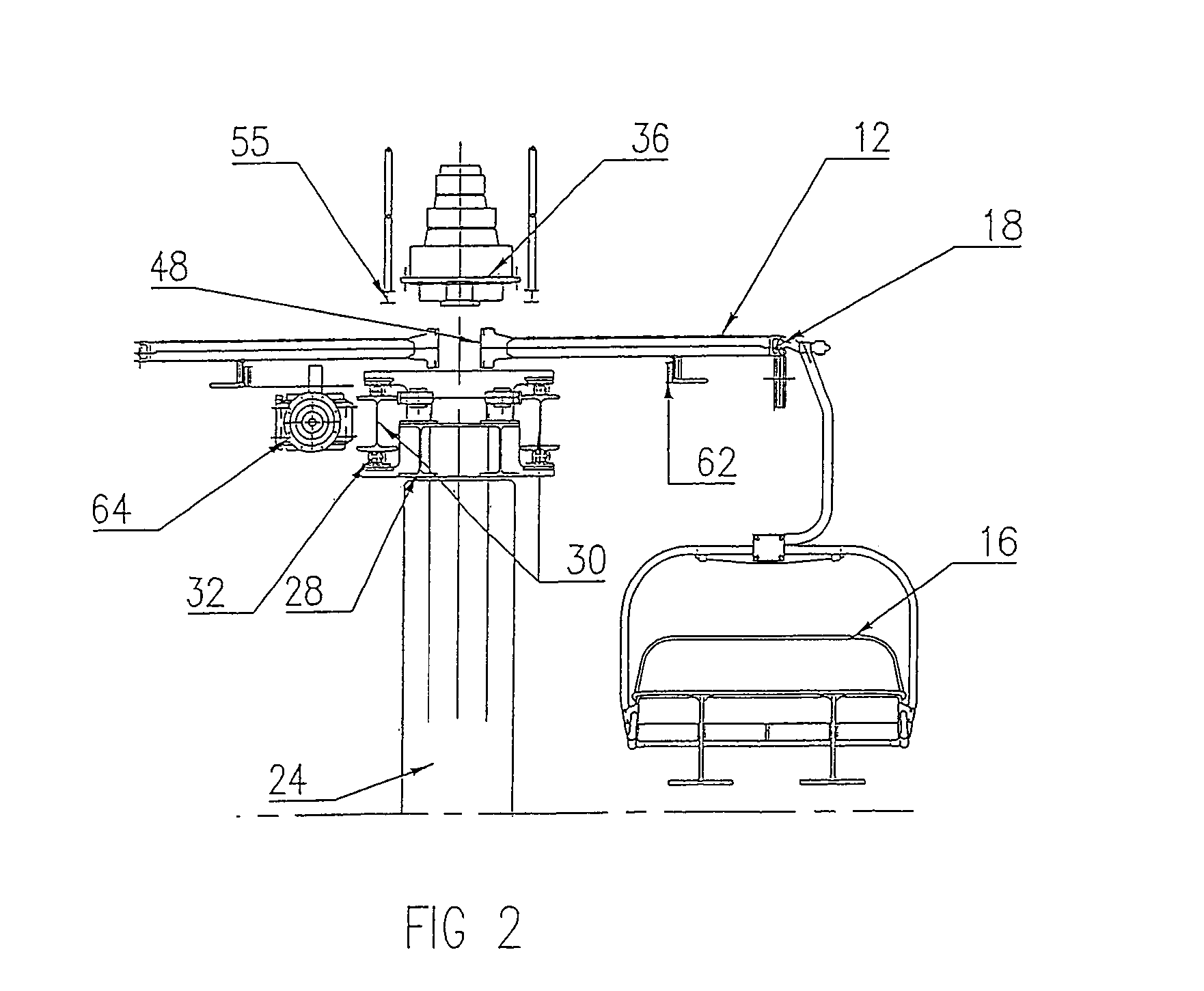
[0020]In FIGS. 1 to 4, an overhead carrying-hauling rope 10 of a chair runs round a vertical-axis bull-wheel 12 housed in an end station or terminal 14. The rope 10 extends in an endless loop along an up-line and a down-line, and chairs 16, one of which is represented in FIG. 2, are hooked onto the rope 10 at regular intervals by fixed securing grips 18.

[0021]The terminal 14 illustrated in FIG. 1 is a down-hill drive terminal wherein the horizontal bull-wheel 12 is driven in rotation by a geared motor mechanism 20 extending perpendicularly to the bull-wheel 12, the assembly being supported by a support device 22 with a predetermined stagger in the heightwise direction.

[0022]The support device 22 is composed of a fixed concrete base 24 anchored to the ground, and a horizontal metal frame 26 comprising fixed l-shaped sections 28, and a carriage 30 mounted with horizontal translation by means of roller parts 32.

[0023]The bull-wheel 12 and geared motor mechanism 20 are fitted on one of ...


PUM


Abstract

A bull-wheel of a fixed carrying-hauling rope chair lift is driven by a geared motor mechanism having a coaxial shaft line extending perpendicularly to the bull-wheel in a substantially vertical direction. The geared motor mechanism is composed of an electric motor and a mechanical speed reducer forming two independent modules arranged on opposing sides of the bull-wheel, which is fitted on a movable carriage to provide mechanical tensioning of the rope.

Description

BACKGROUND OF THE INVENTION[0001]The invention relates to a transport chair lift with a single overhead carrying-hauling rope and fixed grips for securing the chairs, comprising a bull-wheel on which the rope runs, and means for positioning the vertical-axis bull-wheel on a carriage mounted in the terminal on a support device for use as a drive wheel driven by a geared motor mechanism and / or as a tensioning wheel.STATE OF THE PRIOR ART[0002]The vertical-axis drive wheel of a fixed single carrying-hauling rope chair lift is conventionally rotatably driven by a ring and pinion transmission system enabling rotational movement originating from a geared motor arranged horizontally on a raised platform of the terminal to be transmitted at right angles. Implementation of such a kinematic transmission system is complicated and occupies a large longitudinal space in the terminal. The diversity of the sub-assemblies and the equipment assembly and adjustment time increase the number of operati...

Claims


Application Information

Patent Timeline
Patent Type & Authority Patents(United States)
IPC IPC(8): B61B12/00B61B11/00B61B12/10
CPCB61B12/10B61B12/007
Inventor MORAND, YANNICKTAMISIER, FRANCKIE
Owner POMAGALSKI SA
Learn More