
Component to component sealing method

a technology of components and sealing methods, applied in the direction of valve housings, hose connections, manufacturing tools, etc., can solve the problems of compromising the integrity of the connection, difficult to properly align the mating pieces, and high cost of o-rings, so as to reduce the risk of o-ring damage, reduce the credibility of compression, and facilitate manufacturing

Inactive Publication Date: 2006-05-02
ENTEGRIS INC
View PDF3 Cites 12 Cited by
  • Summary
  • Abstract
  • Description
  • Claims
  • Application Information

AI Technical Summary

Benefits of technology

"The invention is a coupling that uses structure on components to seal them. It consists of a male protruding portion, a recessed female receiving portion, and a clamping means. The male protruding portion has a fluid flow duct and a primary sealing surface. The recessed portion has a circular perimeter, an inwardly projecting annular ring, a first cooperating stop surface, a second stop surface, and a fluid flow duct. The male protruding portion and the recessed portion form a continuous bore for fluid flow. The coupling has tolerances less critical than other known systems and is self-centering. It provides a positive stop and optimum compression of the annular ring. The loading of the sealing surfaces is at an angle offset from the engagement direction."

Problems solved by technology

These O-rings are expensive and are subject to degradation and are typically considered to be single use.
These connections have the disadvantage that they must be precisely machined, i.e., tolerances of 0.0005 inches, and it can be difficult to properly align the mating pieces.
Moreover, such connections are vulnerable to nicks and scratches which can compromise the integrity of the connection.

Method used


Image

  • Component to component sealing method
  • Component to component sealing method
  • Component to component sealing method

Examples


Embodiment Construction

[0036]The plastic coupling according to the present invention can be used in a variety of applications, such as for coupling two tubular pipe portions for coupling tubular pipe portions to items such as valves or manifolds, or for coupling a valve to a manifold.

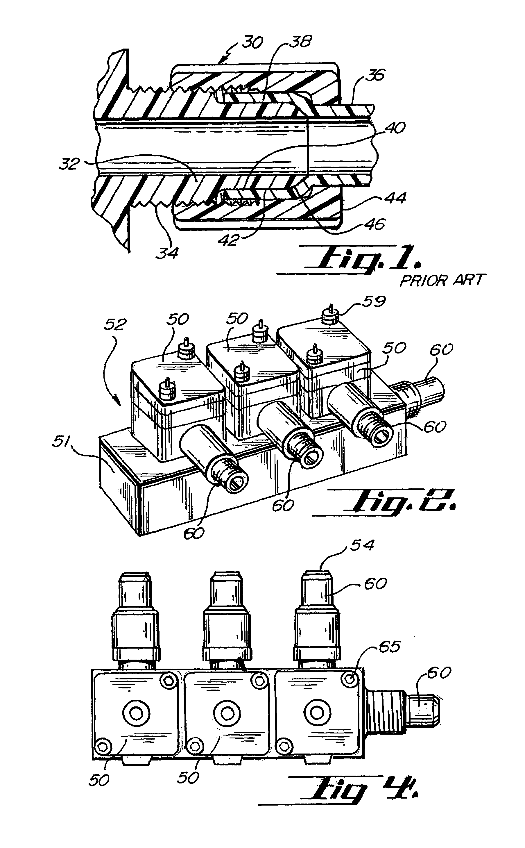
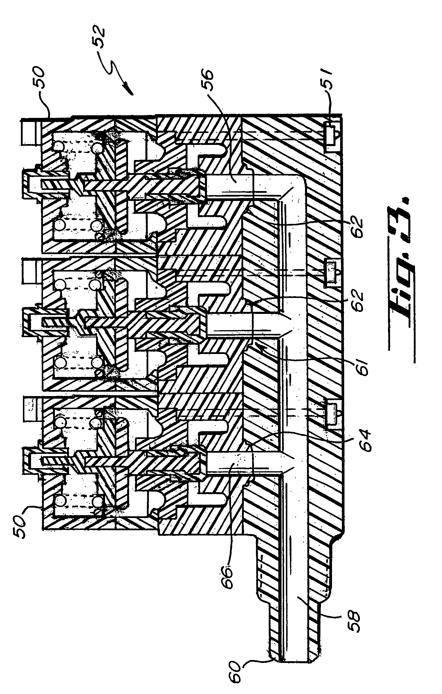
[0037]Referring to FIGS. 2, 3 and 4, valves 50 mounted on a manifold 52, in accordance with one embodiment of the invention, are illustrated. The valves 50, in this embodiment are shown as diaphragm valves conventionally pneumatically operated and have two flow ducts which for purposes of illustration are designated as a fluid inlet 54 and a fluid outlet 56. Obviously, the fluid flow can be in either direction. The manifold 52 may be configured substantially as a block 51 with a fluid flow path 58 extending therethrough. The block manifold 52 at the bore 58 may be connected with a FLARETEK® type coupling 60 known in the industry. Similarly each valve inlet may be suitably attached to tubing by way of FLARETEK® connections 60....


PUM

PropertyMeasurementUnit
compressive forceaaaaaaaaaa
shapeaaaaaaaaaa
pressureaaaaaaaaaa

Abstract

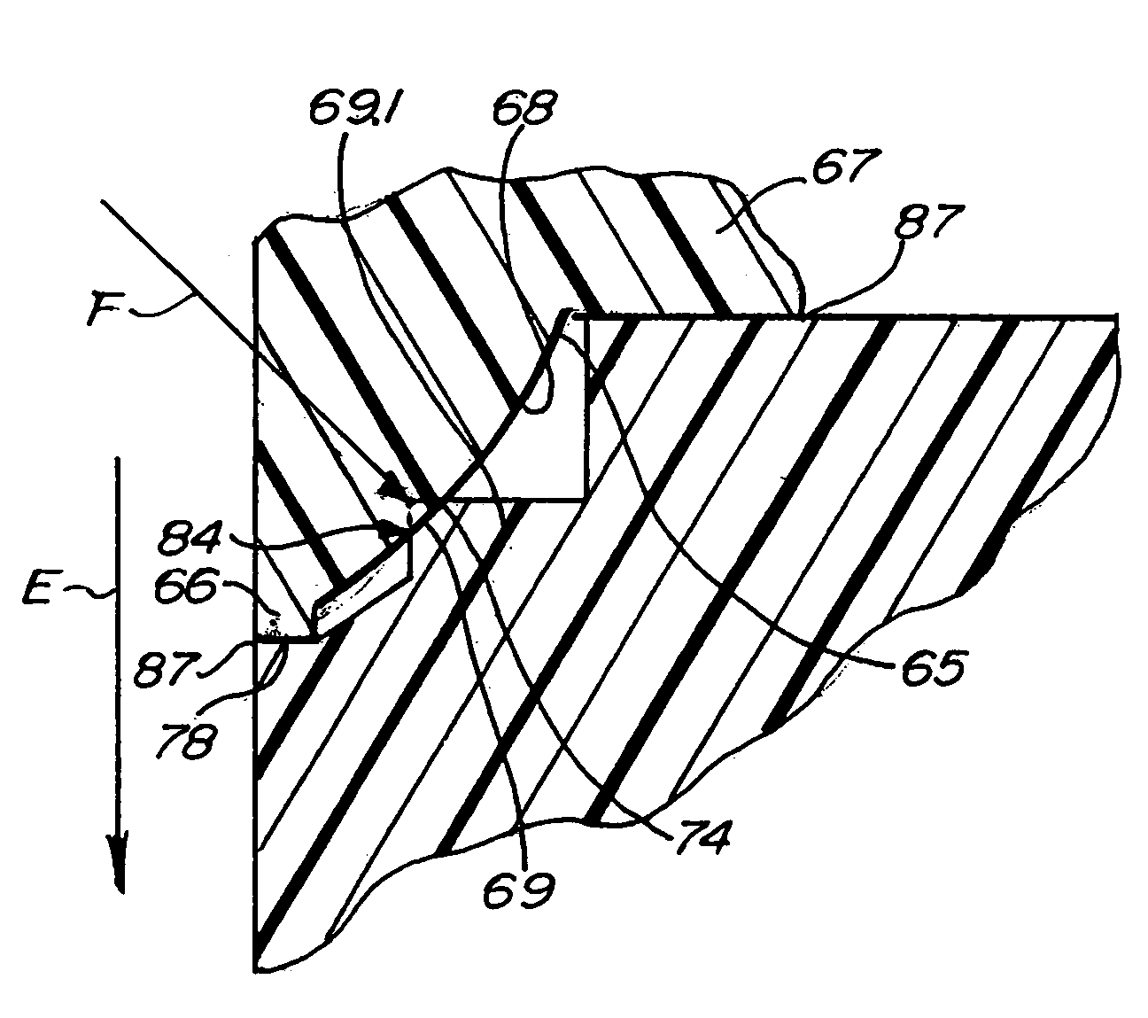
A method for sealingly coupling a first component and a second component. The method includes forming a polymer male portion attached to the first component. The male portion has a first axis and a first bore extending therethrough. The male portion has a first stop surface, a second stop surface and an annular sealing portion intermediate the first stop surface and the second stop surface. The method also includes forming a polymer female portion attached to the second component. The female portion has a second axis and a second bore extending therethrough. The female portion has a third stop surface, a fourth stop surface and an annular ring intermediate the third stop surface and the fourth stop surface. The male portion is urged towards the female portion so that at least one of the first stop surface is adjacent the third stop surface or the second stop surface is adjacent the fourth stop surface. The annular ring is subjected to a compressive force in an oblique direction with respect to at least one of the first axis and the second axis by contact with the annular sealing portion.

Description

REFERENCE TO RELATED APPLICATIONS[0001]This is a Continuation of application Ser. No. 10 / 169,241 filed Nov. 25, 2002, now U.S. Pat. No. 6,652,008, which in turn was filed under 35 U.S.C. § 371 based upon PCT / US00 / 35537, filed Dec. 29, 2000, which claimed priority under 35 U.S.C. § 119 to U.S. Provisional Application No. 60 / 173,905 filed Dec. 29, 1999.FIELD OF THE INVENTION[0002]This invention relates to fluid flow components; more particularly the invention relates to fluoropolymer couplings.BACKGROUND OF THE INVENTION[0003]Numerous industries and many applications utilize metallic tubes, fittings, and various other “plumbing” components for handling and controlling critical fluid flow. Such components may be made of copper, stainless steel, and steel. Where the fluids being handled are under significant pressure or where containment integrity is critical, seals such as O-rings and flexible flat gaskets are typically utilized.[0004]In particular applications such as semiconductor pr...

Claims


Application Information

Patent Timeline
Patent Type & Authority Patents(United States)
IPC IPC(8): B21D39/00F16K27/00F16L19/02F16L41/02
CPCF16K27/003F16L19/02F16L39/00F16L19/0225Y10T29/49909Y10T29/49908
Inventor FISCHER, STEVEN A.STEIN, MICHAEL A.KUBESH, JEFFREY C.EDLUND, TODD J.DONOHO, JAMESSODERSTROM, ERICSTOICK, MICHAEL
Owner ENTEGRIS INC
Learn More