Image processing method and apparatus, and profile management method
a technology of image processing and profile management, applied in the field of color reproduction process of printers, can solve the problems of global method such as color masking method, strong nonlinear output and inability to sufficiently approximate the characteristics of color printers and printing presses in all color ranges, and achieve the effect of precise color reproduction
- Summary
- Abstract
- Description
- Claims
- Application Information
AI Technical Summary
Benefits of technology
Problems solved by technology
Method used
Image
Examples
first embodiment
[Arrangement]
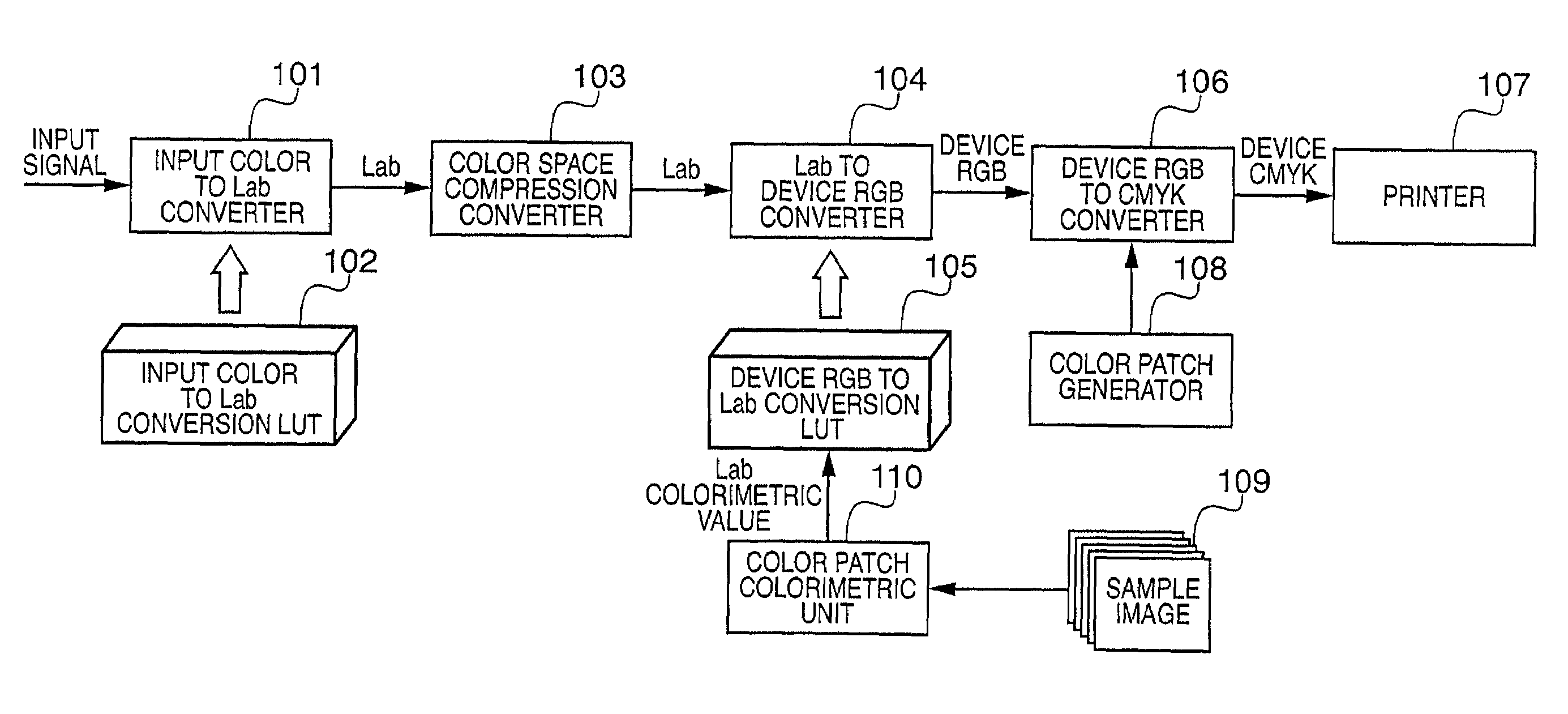
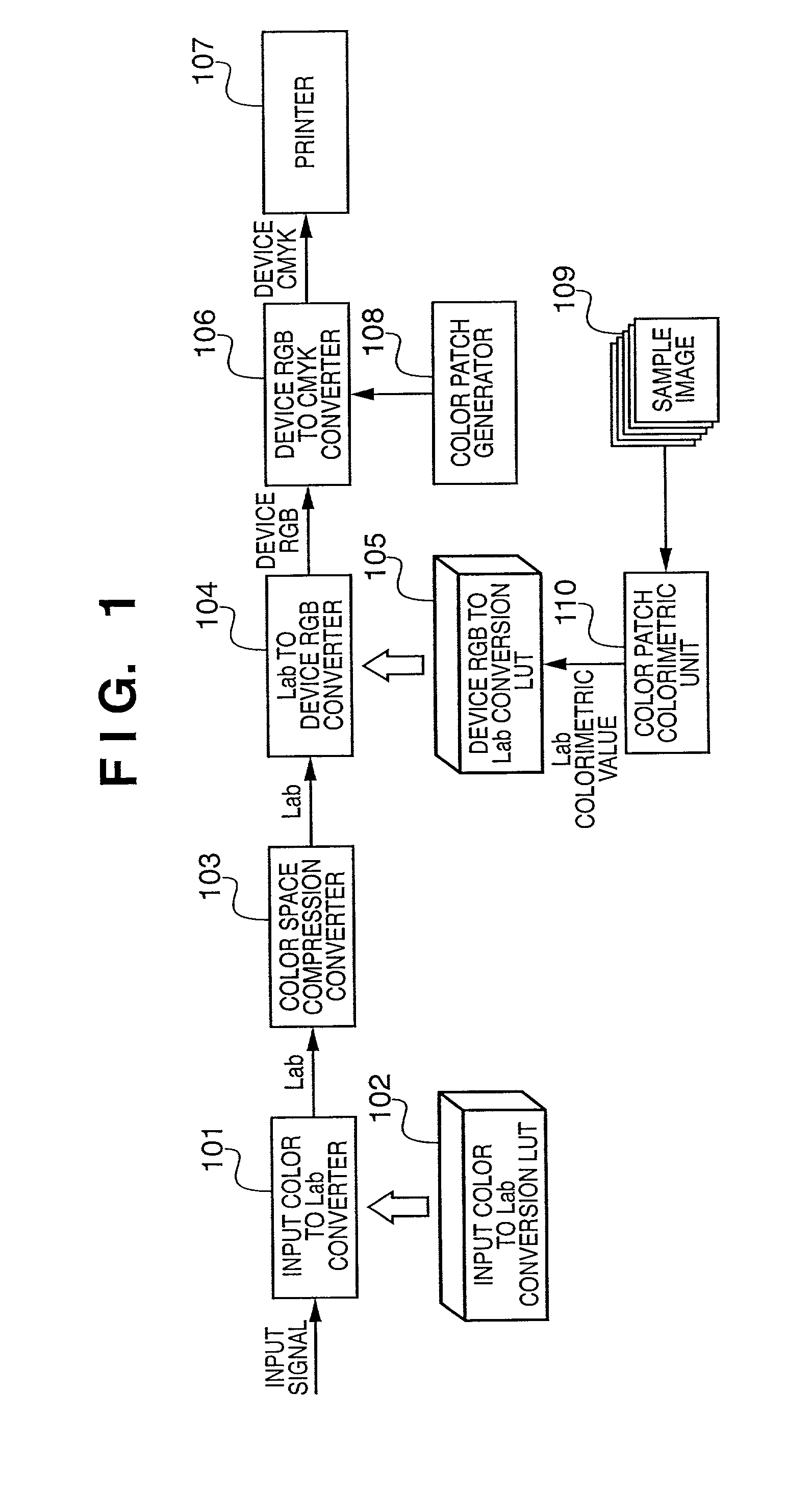
[0047]FIG. 1 is a block diagram showing the arrangement of an image processing apparatus of this embodiment.
[0048]A signal input to the image processing apparatus shown in FIG. 1 is an image signal of a color space depending on a given device, and may be an RGB signal which represents an image read from a document by a given scanner or a CMYK signal to be output to a given printer. When the first embodiment is applied to a copying machine, the input signal is an RGB signal that represents an image read by a scanner. When this embodiment is applied to proof (test print, calibration print), the input signal is a CMYK signal to be output to a printing press as a target.
[0049]Such input signal is input to an input color to Lab converter 101, and is converted into a signal of an Lab color space as a device-independent color space. This conversion is implemented by LUT conversion using an input color to Lab conversion LUT 102.
[0050]In the input color to Lab conversion LUT 102...
second embodiment
[0069]An image processing apparatus according to the second embodiment of the present invention will be explained below. Note that the same reference numerals in this embodiment denote the same parts as in the first embodiment, and a detailed description thereof will be omitted.
[0070]FIG. 9 is a block diagram showing the arrangement of the image processing apparatus of the second embodiment. The image processing apparatus of the second embodiment is different from that of the first embodiment in that a signal of a device-independent color space is converted into a signal of a color space of the printer 107 using an LUT in the same manner as in a case wherein an input signal is converted into a signal of a device-independent color space.
[0071]An Lab to CMYK converter 803 converts an Lab signal into a signal of a CMYK color space which depends on the printer 107 using an Lab to CMYK conversion LUT 804. The CMYK signal output from the Lab to CMYK converter 803 is sent to the printer 10...
third embodiment
[0076]An image processing apparatus according to the third embodiment of the present invention will be described below. Note that the same reference numerals in this embodiment denote the same parts as in the first embodiment, and a detailed description thereof will be omitted.
[0077]FIG. 10 is a block diagram showing the arrangement of the image processing apparatus of the third embodiment, which has an arrangement for inputting an input signal of an sRGB color space that becomes a standard color space in the Internet in recent years. The sRGB color space has specific correspondence with an XYZ color space, and can be considered as a device-independent color space. Hence, when an sRGB value is converted into an XYZ or Lab value, and then undergoes the aforementioned conversion from the Lab color space into a printer color space, the printer 107 can reproduce an image expressed by the signal of the sRGB color space.
[0078]Referring to FIG. 10, an sRGB to CMYK converter 901 converts an...
PUM
 Abstract
Description
Claims
Application Information
 - R&D
- Intellectual Property
- Life Sciences
- Materials
- Tech Scout
- Unparalleled Data Quality
- Higher Quality Content
- 60% Fewer Hallucinations
Browse by: Latest US Patents, China's latest patents, Technical Efficacy Thesaurus, Application Domain, Technology Topic, Popular Technical Reports.
© 2025 PatSnap. All rights reserved.Legal|Privacy policy|Modern Slavery Act Transparency Statement|Sitemap|About US| Contact US: help@patsnap.com


