
Emergency anti-torque thruster system

Active Publication Date: 2006-04-25
EATTS
View PDF21 Cites 61 Cited by
  • Summary
  • Abstract
  • Description
  • Claims
  • Application Information

AI Technical Summary

Benefits of technology

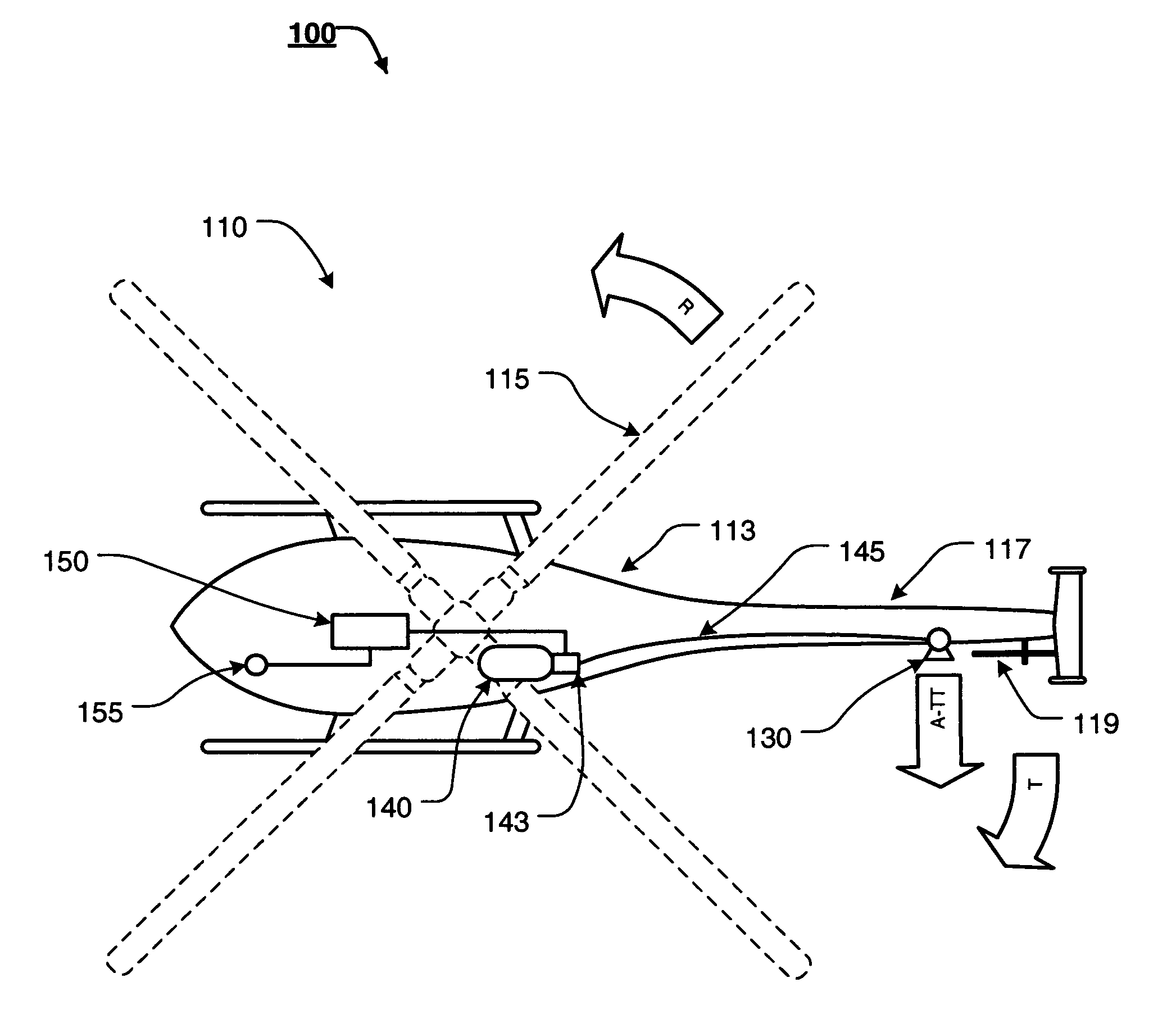
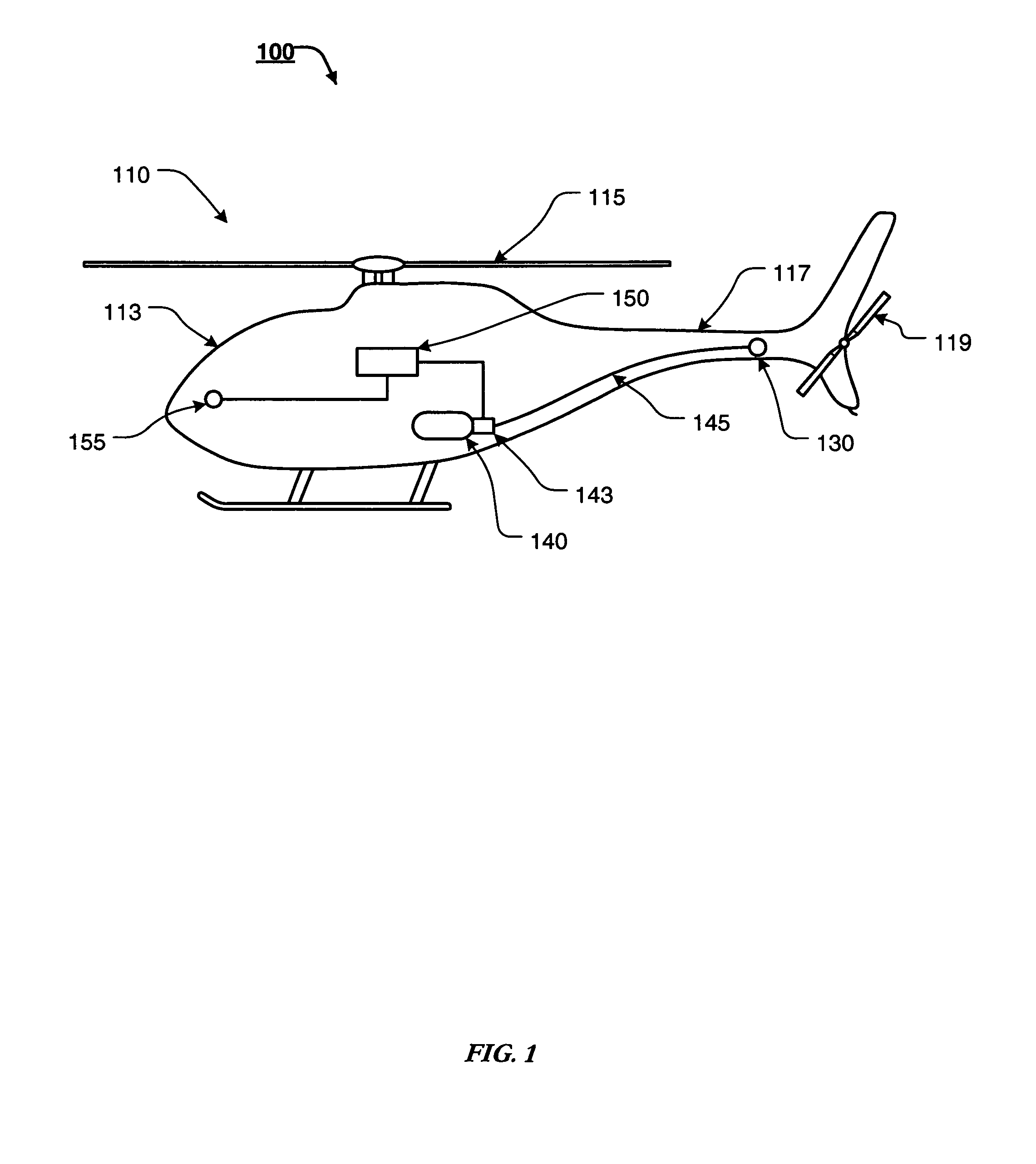
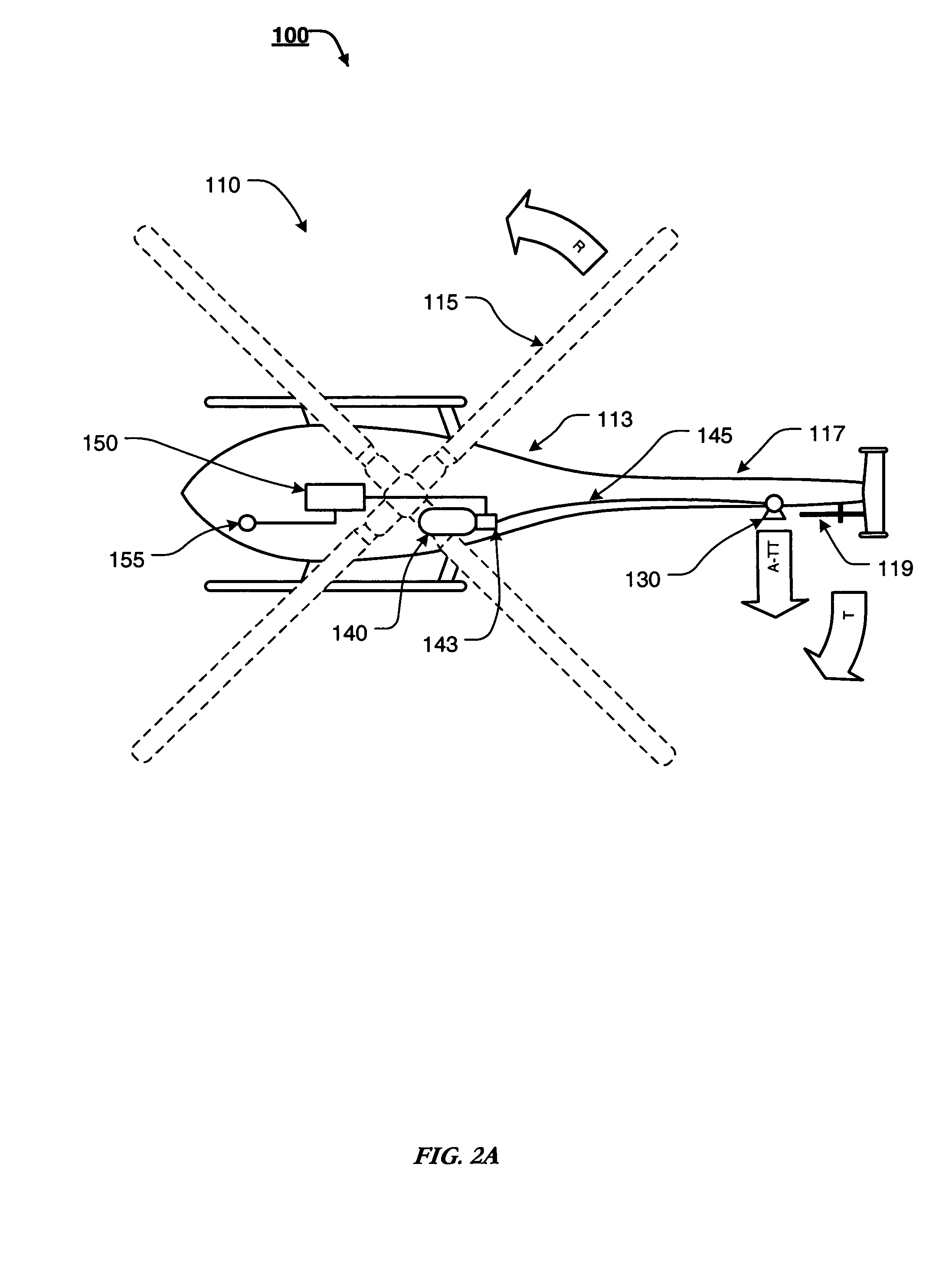
[0016]Accordingly, this invention provides an emergency anti-torque thruster system, which is capable of at least partially counteracting the torque of the main rotor blades of a helicopter that has experienced tail rotor malfunction or failure.

Problems solved by technology

Unfortunately, while helicopters are powerful and useful aircraft, if the helicopter's main anti-torque system, i.e., the helicopter's tail rotor or second, counteracting rotor fails, the torque from the main rotor will spin the body of the helicopter in the opposite direction of the rotation of the rotor.

Method used


Image

  • Emergency anti-torque thruster system
  • Emergency anti-torque thruster system
  • Emergency anti-torque thruster system

Examples


Embodiment Construction

[0029]For simplicity and clarification, the design factors and operating principles of the anti-torque thruster system according to this invention are explained with reference to various exemplary embodiments of an anti-torque thruster system according to this invention. The basic explanation of the design factors and operating principles of the anti-torque thruster system is applicable for the understanding, design, and operation of the anti-torque thruster system of this invention.

[0030]Furthermore, it should be appreciated that, for simplicity and clarification, the embodiments of this invention will be described with reference to the helicopter's main rotor turning left, or counter-clockwise, when viewed from above. The main rotor of helicopters manufactured in the United States typically rotates counter-clockwise. Therefore, if the helicopter's tail rotor fails, the torque from the main rotor will spin the body of the helicopter right, or clockwise, when viewed from above. Howe...


PUM


Abstract

An anti-torque thruster system implemented onboard an aircraft comprising a propulsion means coupled to the aircraft, wherein the propulsion means is capable of providing a measure of anti-torque thrust to the aircraft, a fuel storage container coupled to the propulsion means via a fuel delivery conduit, wherein the fuel storage container is capable of storing an appropriate fuel for the propulsion means, a valve means disposed between the fuel storage container and the propulsion means, wherein the valve means may be useable to regulate the flow of fuel from the fuel storage container to the propulsion means, and a controller for controlling the valve means to regulate the flow of fuel from the fuel storage container to the propulsion means, wherein the controller is capable of receiving input from at least one input device.

Description

BACKGROUND OF THE INVENTION[0001]1. Field of the Invention[0002]This invention relates generally to anti-torque thruster systems. In particular, the present invention relates to an emergency anti-torque thruster system.[0003]2. Description of Related Art[0004]Helicopters and other rotary-wing aircraft are typically lifted and propelled by one or more large horizontal rotors, each comprising multiple, angled or angleable, rotor blades. Helicopters are able to fly because forward motion of the angled rotor blades forces air downwards, creating lift, which forces the rotor blades, and, in turn, the helicopter suspended beneath, upwards.[0005]Useful flight requires that the helicopter's altitude, yaw (movement in the right-left horizontal direction), pitch (tilting forward and back), and roll (tilting sideways) be controlled simultaneously. For yaw control, the pitch, or angle-of-attack, of the helicopter's tail rotor blades is typically varied to alter the amount of thrust produced, th...

Claims


Application Information

Patent Timeline
IPC IPC(8): B64C27/06
CPCB64C27/006B64C27/82B64C2027/8245
Inventor KIRK, CHARLES T.HODDER, LEGAL REPRESENTATIVE, VIRGINIA L.MOORE, DECEASED, GROVER L.
Owner EATTS
Learn More