
Vehicle power source supporting structure

a technology for supporting structures and power sources, applied in the direction of electric propulsion mountings, electric devices, jet propulsion mountings, etc., can solve the problems of insufficient drive safety/ride quality feeling, difficult to adopt a double vibration isolation structure, and inability to completely shut o

Active Publication Date: 2006-04-25
HONDA MOTOR CO LTD
View PDF12 Cites 16 Cited by
  • Summary
  • Abstract
  • Description
  • Claims
  • Application Information

AI Technical Summary

Benefits of technology

[0012]The main problem of the present invention is to provide the supporting structure of a vehicle power source in which a vibration feeling in the front / rear direction (hereinafter referred to as longitudinal direction) as well as in the right / left direction (hereinafter referred to as lateral direction) of a vehicle body can be eliminated so as to surely and sufficiently obtain a drive-safety / ride-quality feeling.
[0018]Because the height of the center of elasticity, created by the plurality of mount members consisting of the primary and secondary weight sharing mount members as a whole, is set at a higher position than the height of the gravity center of the power source, the supporting structure enables vibration feelings in the longitudinal direction as well as in the lateral direction of the vehicle body to be eliminated.
[0019]Accordingly, the supporting structure enables a vibration isolation effect and a drive-safety / ride-quality feeling with a sense of unity between the power source and vehicle body to be surely and sufficiently obtained.
[0021]According to such a supporting structure, in the secondary weight sharing mount members elastically supporting both sides of the power source, the spring component elasticity of the vertical direction is set softer (a lower spring constant) and that of the longitudinal or lateral direction is set more rigid (a higher spring constant). Thus, the secondary weight sharing mount members make it difficult for a passenger to experience a vibration, where the roll / pitch of a driving source and a vibration transmission from body side frames can be curbed.
[0024]Moreover, because the sub-frame is supported under the body side frames through the sub-frame support mounts, it breaks up, falls downward from the body side frames, and separates in the case of a vehicle collision. Therefore, a passenger compartment of a vehicle may go over the power source in the case of the vehicle collision, so it can be prevented from being crushed by the driving source.

Problems solved by technology

Moreover, there is a problem that a passenger easily experiences a roll / pitch feeling of the power source and cannot get a sense of unity between the power source and vehicle body and so a sufficient drive-safety / ride-quality feeling cannot be obtained.
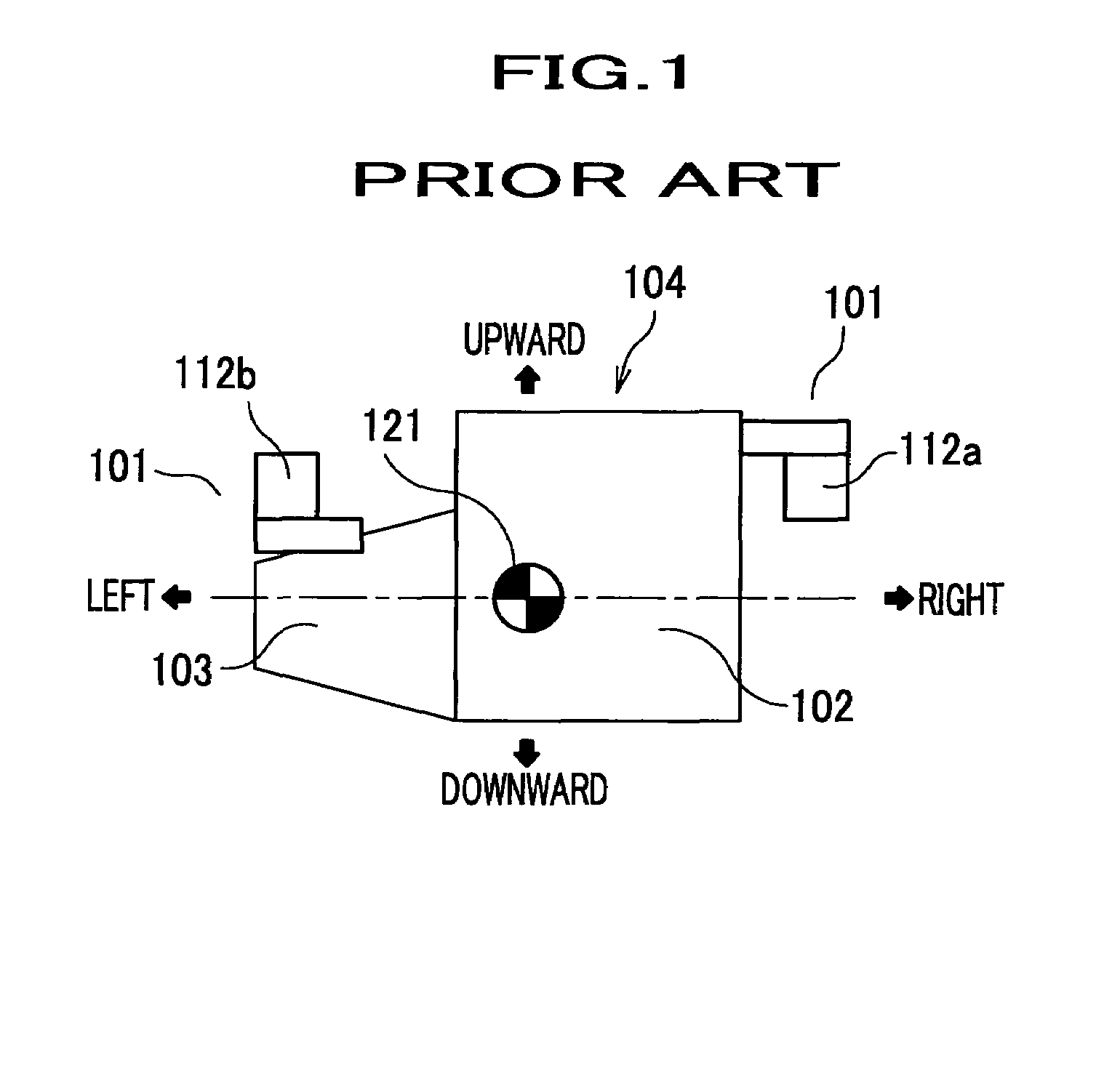
In this configuration, it is difficult to adopt a double vibration isolation structure such that mount members 101 are placed and held on the side frame and elastically supported by a vehicle body frame, compared to the gravity center mount type of supporting structure.
Moreover, there is a problem that routes from the side engine mount 112a and transmission mount 112b at both sides to a cabin are short, so a sound and vibration which cannot be completely shut off by the mount members 101 are easily transmitted to a passenger.

Method used


Image

  • Vehicle power source supporting structure
  • Vehicle power source supporting structure
  • Vehicle power source supporting structure

Examples


Embodiment Construction

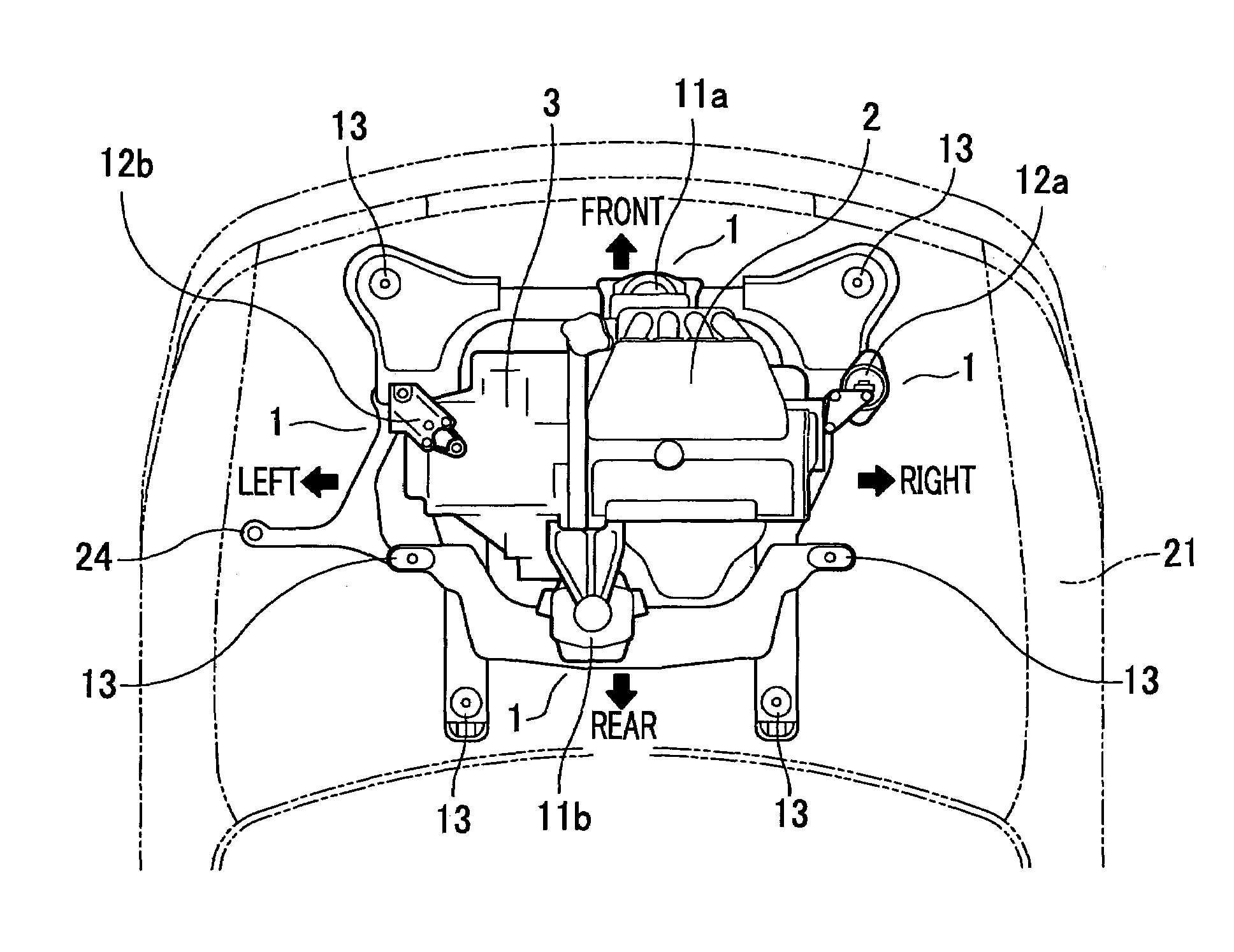
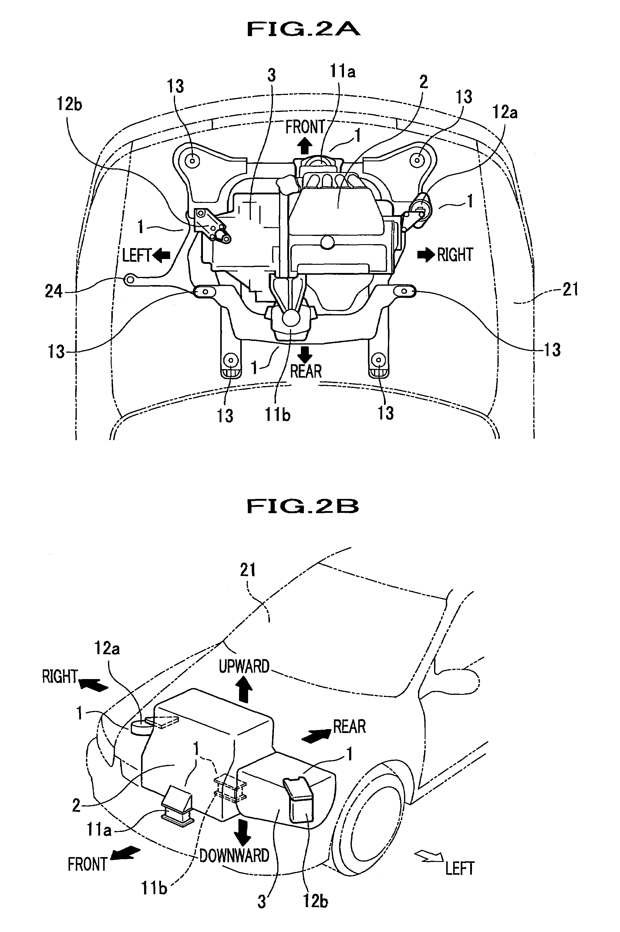
[0035]One preferred embodiment of the invention will be described in detail hereinafter with reference to the accompanying drawings.

a. Supporting Structure of Vehicle Power Source

[0036]FIGS. 2A and 2B are a plan view and perspective view showing a general configuration of the supporting structure related to one embodiment of the invention, respectively. FIGS. 3A, 3B, and 3C are a plan view, rear view, and side view showing a schematic configuration of the supporting structure related to embodiment of the invention, respectively.

[0037]In the embodiment illustrated, the supporting structure is designed to be used for the support of an engine 2 which is the vehicle power source to a vehicle body 21 through a plurality of mount members 1 having elasticity so that the engine is elastically supported by the vehicle body.

[0038]Here, the engine 2 is designed so that a transmission 3 is connected to one end of its crank shaft (not shown in any drawing) and the crank shaft is laterally dispos...


PUM


Abstract

A supporting structure of a vehicle power source consists of a plurality of mount members having elasticity through which a power source is mounted on a vehicle body; first mount members for primarily sharing the weight of the power source and at least one of the first mount members, which is supported by the vehicle body at a first height lower than the height of a gravity center of the power source, is attached to a sub-frame; and second mount members for secondarily sharing the weight of the power source and the second mount members, which are attached to the vehicle body at a second height higher than the gravity center of the power source. A height of a center of elasticity of the supporting structure defined by the first and second mount members is set to be higher than a height of the gravity center of the power source.

Description

FIELD OF THE INVENTION[0001]The present invention relates to a supporting structure of a vehicle power source used for a vehicle body support of a vehicle power source through a plurality of mount members with elasticity.BACKGROUND OF THE INVENTION[0002]Conventionally, there is a supporting structure for a vehicle power source used in a vehicle body. Such supporting structure types include a gravity center mount type of supporting structure and an inertia bearing main shaft type of supporting structure.[0003]The gravity center mount type is a type in which a center of elasticity is created through mounts, and is substantially accorded with a gravity center of the supporting structure. In this configuration, an engine and transmission are visually placed and held on the mounts, which are provided on frame members such as a sub-frame.[0004]When the engine is lengthwise disposed, the center of elasticity created by the mounts is set higher than the gravity center of the engine in many ...

Claims


Application Information

Patent Timeline
Patent Type & Authority Patents(United States)
IPC IPC(8): B60K1/00B60K5/12
CPCB60K5/1216B60K5/1208
Inventor YOSHIDA, HIROYUKIMIYAGAWA, KAZUOKAMI, HIDEKIWATANABE, SATOSHI
Owner HONDA MOTOR CO LTD
Learn More