
Partition plate for intake port, sand core for forming intake port, and cylinder head

a technology for forming sand cores and intake ports, which is applied in the direction of cylinders, mechanical equipment, machines/engines, etc., can solve the problems of molten metal exuding, thermal expansion, cracks or damage to the cores, etc., and achieves the effect of reducing the positional displacement of the partition plate, improving the quality of the product, and facilitating deburring work

Active Publication Date: 2006-04-25
NISSAN MOTOR CO LTD +1
View PDF5 Cites 18 Cited by
  • Summary
  • Abstract
  • Description
  • Claims
  • Application Information

AI Technical Summary

Benefits of technology

The present invention provides a partition plate for an intake port of a cylinder head that can be manufactured by cast molding and preliminarily set in a sand core. The partition plate is designed to prevent burrs and cracks in the core caused by thermal expansion and to improve the quality of the cast product. The partition plate has end faces and side edges that are cast in by molten metal and a promoter section to promote solidification of the molten metal. The invention also provides a cylinder head with the partition plate preliminarily set and cast in during cast molding.

Problems solved by technology

On the cast molding of the cylinder head, the sand core and the partition plate are exposed to heat of molten metal to result in increases in respective temperatures to cause thermal expansions.
Thus, it is conceivable for the partition plate to pressurize or expand the core, causing cracks or damages to the core, whereby molten metal exudes through the cracks with resultant formation of burrs.
Also, it is conceivable that due to thermal expansion of the partition plate, a locating position of the partition plate is adversely affected on the cast molding of the cylinder head and, additionally, there exists a probability for looseness of the partition plate to occur in the cylinder head, serving as a cast product, after completing the cast molding.
For this reason, it is conceived that not only exceptionally troublesome deburring work is required in subsequent processing depending upon regions at which the burrs occur, but also deterioration occurs in a product quality as a result of positional displacement of the partition plate or the occurrence of looseness inside the cast product.

Method used


Image

  • Partition plate for intake port, sand core for forming intake port, and cylinder head
  • Partition plate for intake port, sand core for forming intake port, and cylinder head
  • Partition plate for intake port, sand core for forming intake port, and cylinder head

Examples


first embodiment

(First Embodiment)

[0085]A first embodiment according to the present invention is described below.

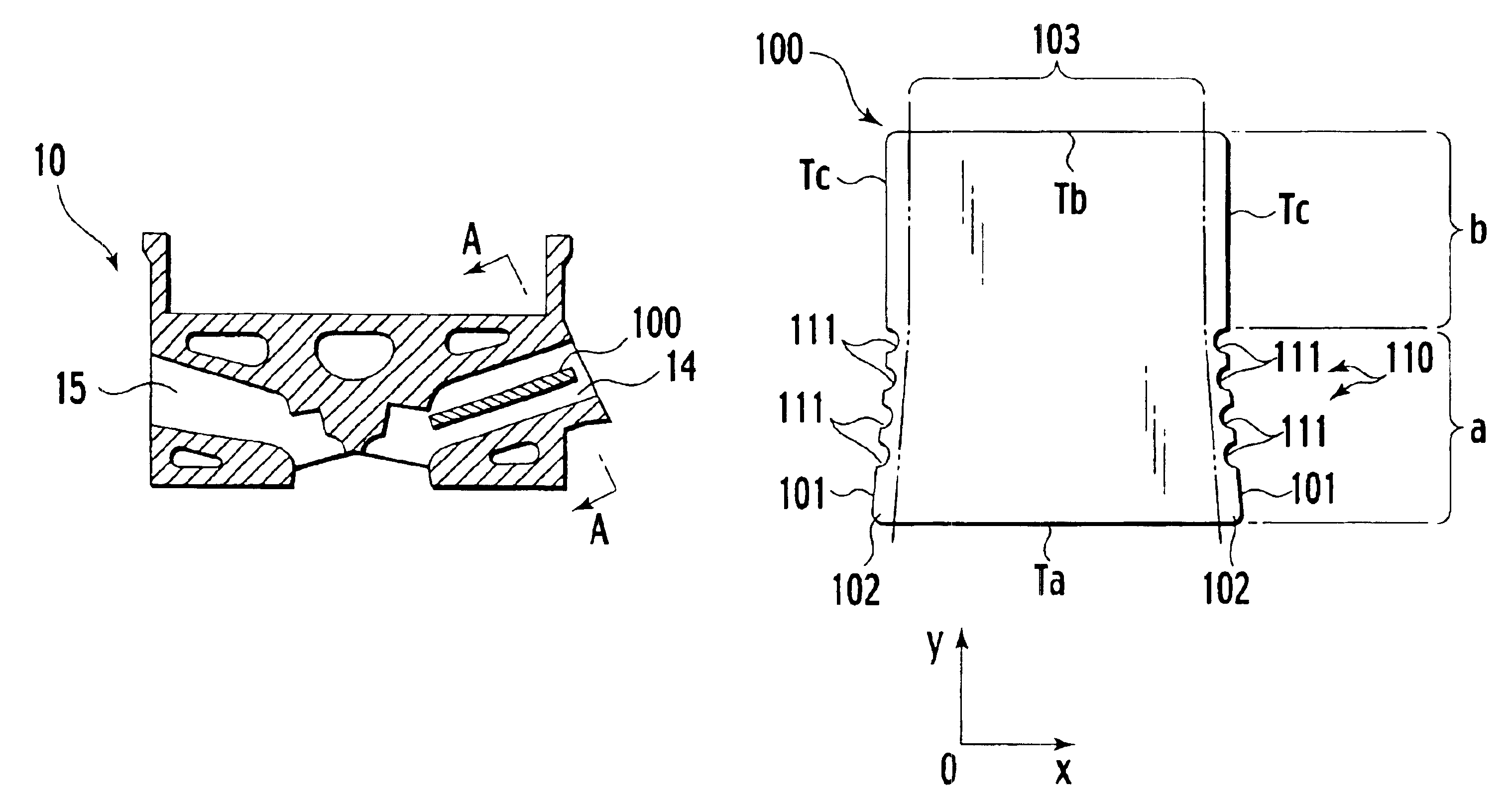
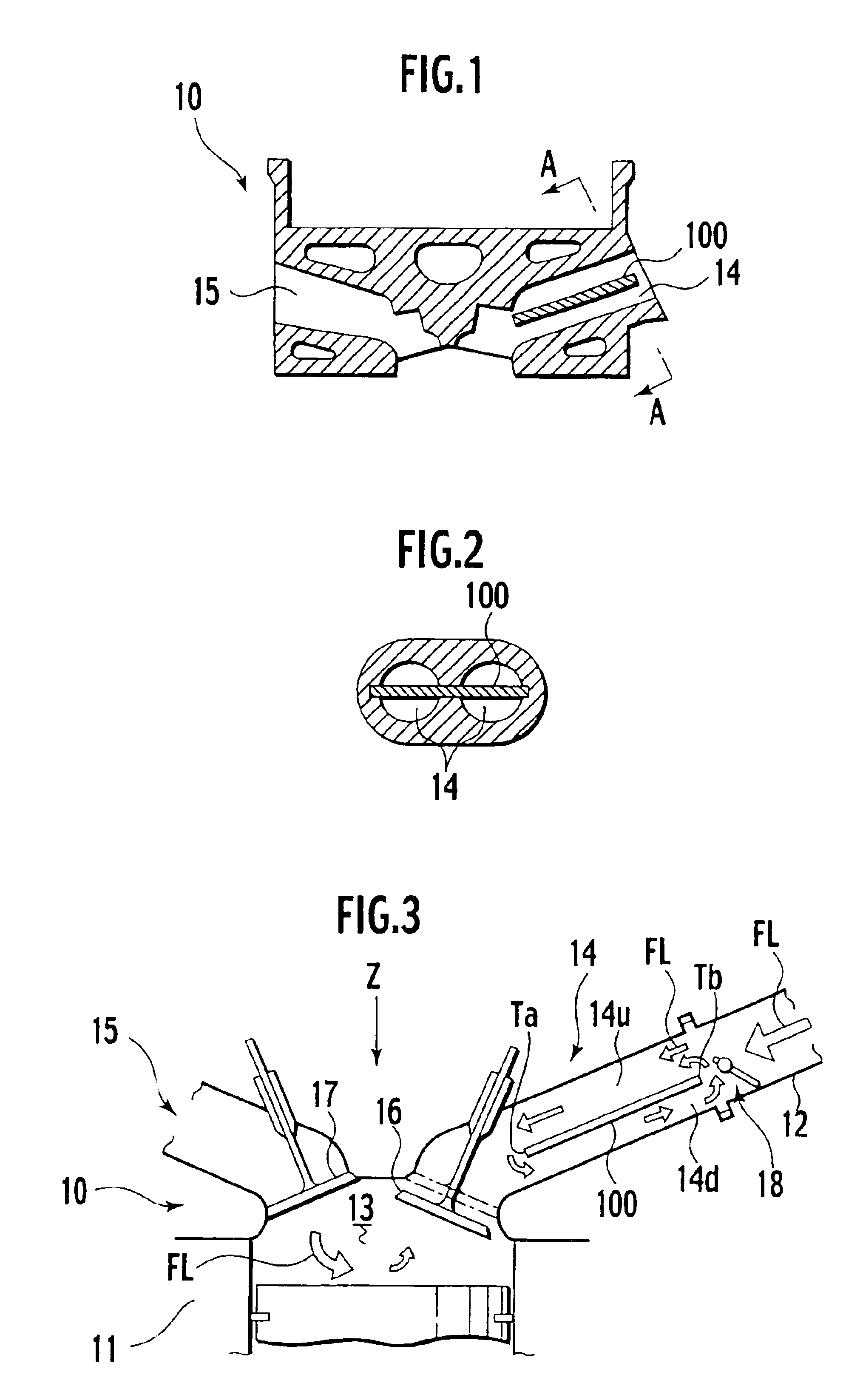
[0086]First, a cylinder head 10 with a partition plate 100 for an intake port 14 is described. Incidentally, throughout the specification, the partition plate 100 for the intake port 14 is also referred to as a “tumble plate 100”.

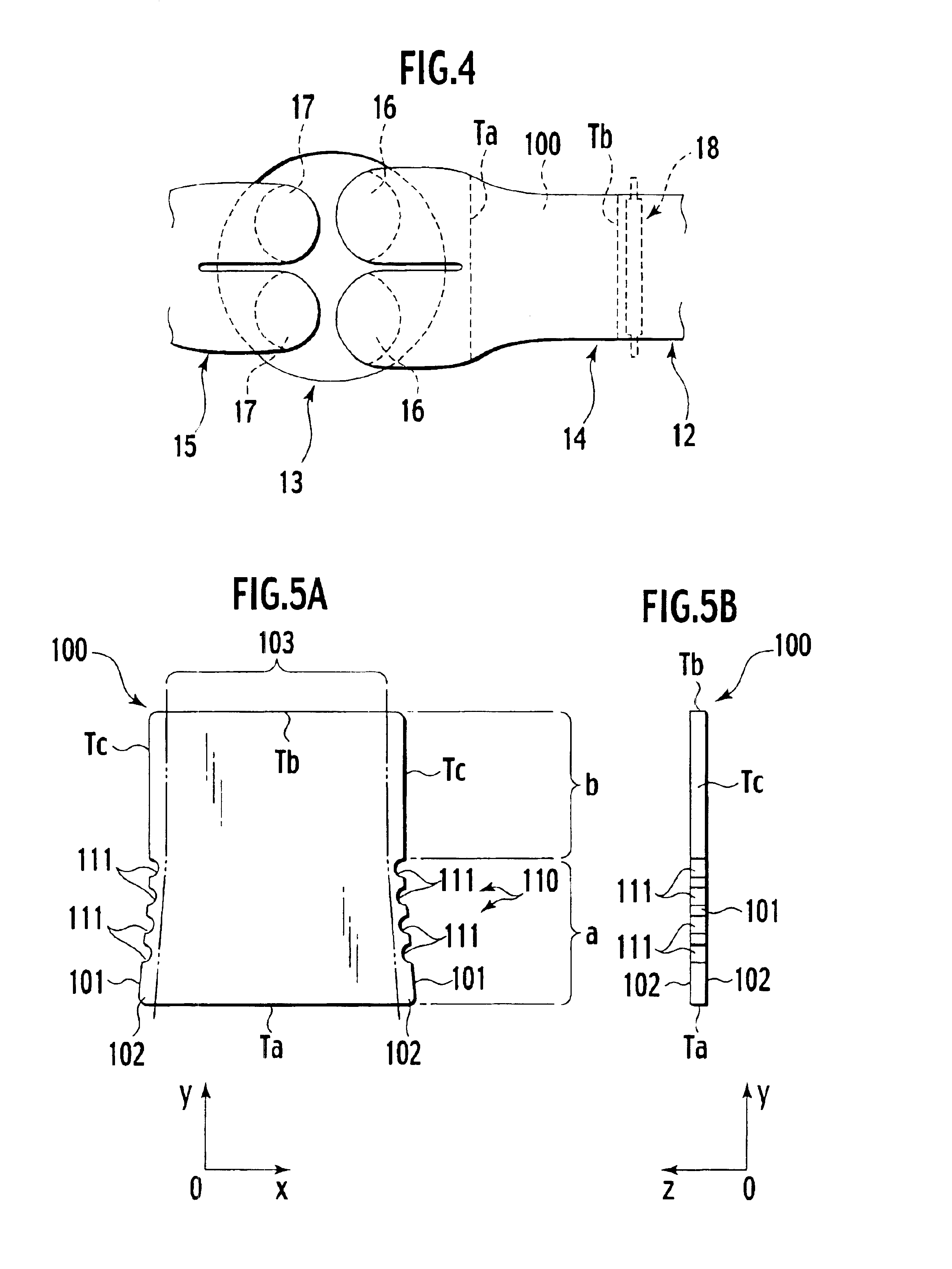
[0087]FIG. 1 is a schematic cross sectional view illustrating a cylinder head 10, of an engine, of the presently filed embodiment; FIG. 2 is a cross sectional view taken on line perpendicular to an axis of the intake port 14 of the cylinder head 10; FIG. 3 is a schematic view illustrating a flow current condition in the cylinder head 10; and FIG. 4 is a schematic plan view of the cylinder head shown in FIG. 3.

[0088]As shown in FIGS. 1 to 3, the cylinder head 10 is set on a top of a cylinder block 11 and has the intake port 14 for introducing intake airflow, composed of air and fuel gas delivered from an intake manifold 12, into a cylinder bore 13 and an exhaust ...

second embodiment

(Second Embodiment)

[0138]Next, a second embodiment according to the present invention is described.

[0139]FIGS. 11A and 11B are a schematic plan view and a schematic side view illustrating a port core 200a in which a tumble plate 100a of the presently filed embodiment is preliminarily set.

[0140]As shown in FIGS. 11A and 11B, the tumble plate 100a of the presently filed embodiment differs from the first embodiment in that regions (forming the solidification promoter section “a”) of the both side edges Tc, in which the promoter portions 110 are provided, have a larger cast-in width than that of the other regions (forming the flat and smooth section “b”) of the both side edges Tc whereas in the first embodiment, the both side edges Tc have a cast-in width in an equal value. Incidentally, other structure is identical to the first embodiment.

[0141]Such a cast-in width may be determined in a suitable dimension depending upon a wall thickness of the intake port 14 and a thickness of the tum...

third embodiment

(Third Embodiment)

[0145]Next, a third embodiment according to the present invention is described.

[0146]FIGS. 12A and 12B are a schematic plan view and a schematic side vice illustrating a port core 200b in which a tumble plate 100b of the present invention is preliminarily set.

[0147]As shown in FIGS. 12A and 12B, the tumble plate 100b of the presently filed embodiment differs from the first embodiment in that the presently filed embodiment takes the form of a structure wherein with the tumble plate 100b of the presently filed embodiment, the promoter portions 110 are formed on the respective side end faces 101 of the both side edges Tc at positions closer to the intake-side distal end Tb whereas in the first embodiment, the promoter portions 110 are located in the positions closer to the cylinder-side distal end Ta. Incidentally, the other structure is similar to that of the first embodiment.

[0148]Depending upon a structure of the intake port 14 and the type of the fuel injection un...


PUM

PropertyMeasurementUnit
thicknessaaaaaaaaaa
widthsaaaaaaaaaa
width L2aaaaaaaaaa

Abstract

A partition plate for an intake port of a cylinder head to be manufactured by cast molding is preliminarily set prior to the cast molding in a sand core applied to form the intake port and then cast in by the cast molding to partition the intake port into a plurality of ports. The partition plate is provided with an intake-side distal end, a cylinder-side distal end, a pair of side edges continuous with the intake-side distal end and the cylinder-sided distal end and to be cast in by molten metal during the cast molding. Each of the pair of side edges having end faces facing in a thickness direction and a side end face continuous with the end faces. The partition plate is further provided with a promoter section provided on at least one of the side end face and the end faces of each of the pair of side edges to promote solidification of the molten metal.

Description

BACKGROUND OF THE INVENTION[0001]The present invention relates to a partition plate for an intake port, a sand core for forming an intake-port and a cylinder head and, more particularly, to a partition plate for an intake port, a sand core for forming an intake-port and a cylinder head which are able to improve a precision in fixing position of a tumble plate in an intake port of a cylinder head.[0002]In recent years, a cylinder of an internal combustion engine includes a cylinder head formed with an intake port in which a partition plate, called as a tumble plate, is set.[0003]Japanese Patent Application Laid-Open Publication No. 2001-193469 (see paragraphs 0011, 0020 and 0022 and FIGS. 1, 3 and 4) discloses a structure wherein an airflow control valve disposed in an intake-side distal end of an intake port is controlled while permitting a partition plate to deflect intake air, introduced from the intake port to a cylinder bore, for intensifying a tumble flow occurring inside the c...

Claims


Application Information

Patent Timeline
Patent Type & Authority Patents(United States)
IPC IPC(8): F02B31/00F02B31/08F02F1/24F02F1/42
CPCF02B31/08F02F1/4242Y10T29/49231Y02T10/146F02F2200/06Y02T10/12F02F1/24
Inventor KATOU, HIROSHIKAJIHARA, HIROHITOYAGETA, KENJINISHIDA, TOSHIYUKIINOSE, MASAMIMASUTA, TATSUYA
Owner NISSAN MOTOR CO LTD
Learn More