Cartridge and drive unit for preventing erroneous insertions of the cartridge

Inactive Publication Date: 2006-04-18
HITACHT MAXELL LTD
View PDF22 Cites 5 Cited by
  • Summary
  • Abstract
  • Description
  • Claims
  • Application Information

AI Technical Summary

Benefits of technology

[0013]Accordingly, it is an exemplified object of the present invention to provide a cartridge, its drive unit, and a system including them that promptly determines the fitness of the cartridge to the drive unit, prevents erroneous insertions of the cartridge, and protecting the cartridge and the drive unit from getting damaged.
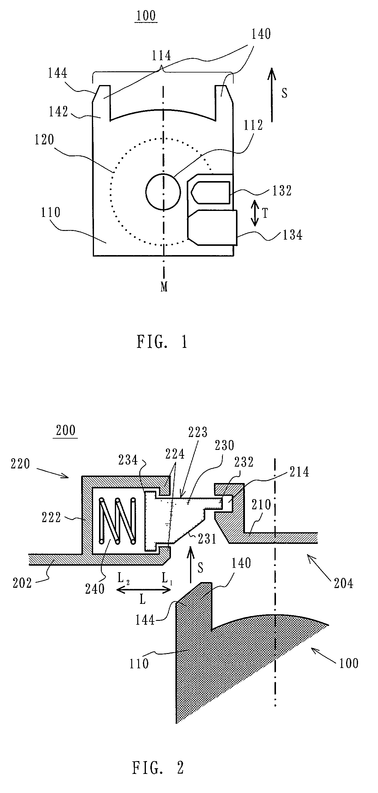
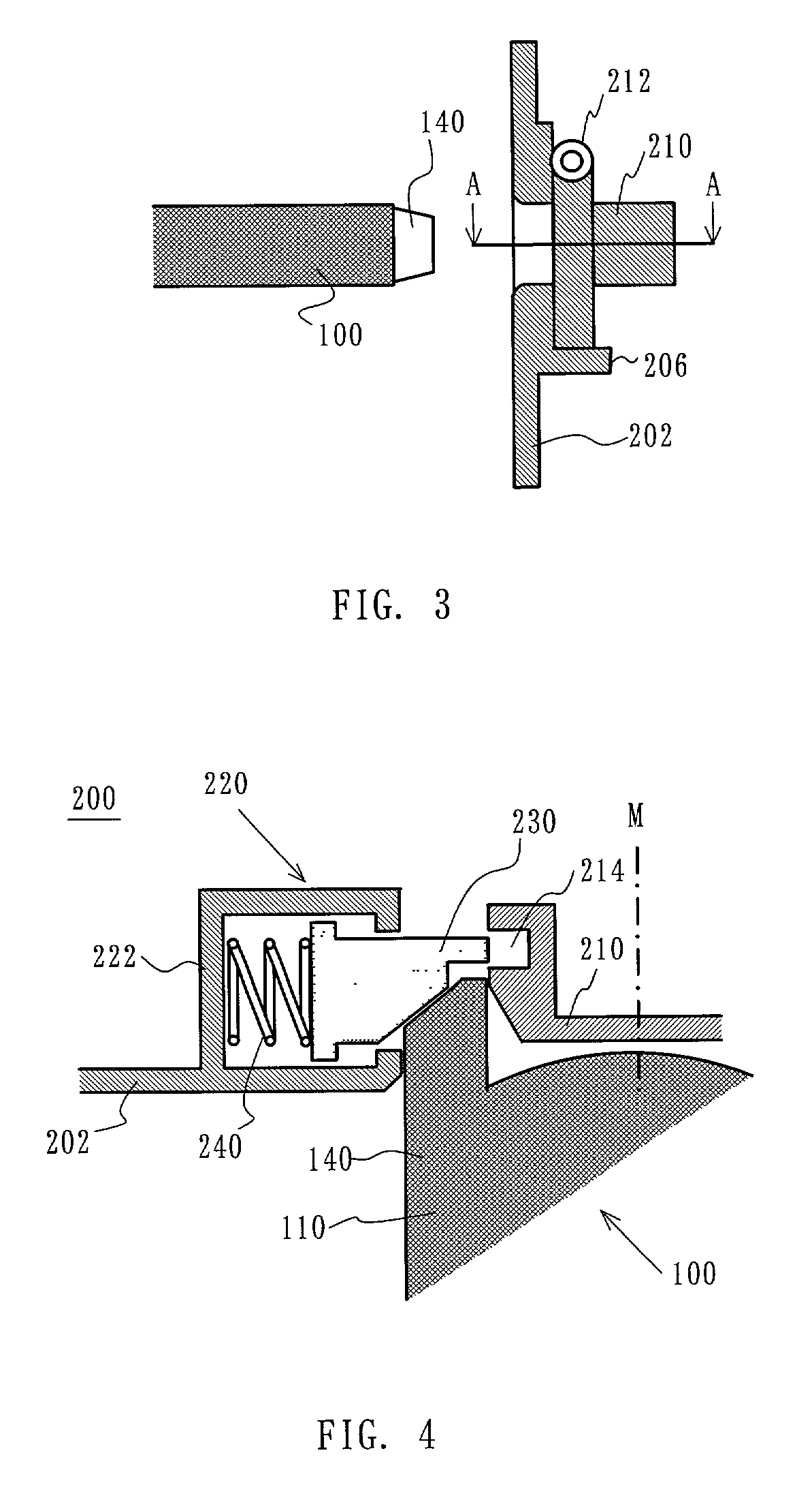
[0017]The cartridge may further include a front surface that is first inserted into the insertion opening, and the unlock member includes a projection that protrudes from the front surface in an insertion direction of the cartridge into the drive unit. Such a projection serves as a key to release a lock. Although it is conceivable to respectively form the front surface and the shutter as a unique shape in its thickness direction, this would thicken the cartridge and it would be difficult to apply this method to the cartridge that has been required to be made thin. Accordingly, the projection is formed ahead from the front surface of the cartridge to prevent the cartridge thick while unlocking the shutter by a simple structure.
[0019]The front surface may include at least one axis of symmetry when the cartridge is viewed from a front of the cartridge, and the unlock member includes a projection located approximately symmetrically with respect to the axis of symmetry, wherein a shape of the front surface may be different from that of the front surface rotated by 180°. Since the projection is located approximately symmetrically with respect to the axis of symmetry, approximately symmetrical force with respect to the axis of symmetry applies onto the shutter without deforming or damaging the shutter when the cartridge is pressed against the shutter. In addition, a shape changing before and after the rotation by 180° of the front surface would prevent an erroneous insertion regarding an orientation of the cartridge, for example, when the cartridge is inserted upside down.

Problems solved by technology

Therefore, erroneous insertions are detectable before the cartridge is inserted into the inside of the drive unit.

Method used


Image

  • Cartridge and drive unit for preventing erroneous insertions of the cartridge
  • Cartridge and drive unit for preventing erroneous insertions of the cartridge
  • Cartridge and drive unit for preventing erroneous insertions of the cartridge

Examples


second embodiment

[0073]A description will now be given of a disk cartridge 100A of a second embodiment according to the present invention, with reference to FIG. 8. Here, FIG. 8(a) is a perspective view of an external appearance of the disk cartridge 100A at its front side with a shutter 134A closed. FIG. 8(b) is a front view of the disk cartridge 100A. FIG. 8(c) is a plane view of the disk cartridge 100A at its backside. FIG. 8(d) is a perspective view of an external appearance of the disk cartridge 100A at the backside shown in FIG. 8(a). FIG. 8(e) is a perspective view of an external appearance of the disk cartridge 100A at its front side with the shutter 134 open. FIG. 8(f) is a perspective view of an external appearance of the disk cartridge 100A shown in FIG. 8(e) at its backside.

[0074]The disk cartridge 100A includes a pair of different shaped projections 140A and 140B at both sides of a front surface 114A of a cartridge case (or shell) 110A. The projection 140A is different from the projecti...

third embodiment

[0080]A description will now be given of a disk cartridge 100B of a third embodiment according to the present invention, with reference to FIG. 9. Here, FIG. 9(a) is a perspective view of an external appearance of the disk cartridge 100B at its front side. FIG. 9(b) is a front view of the disk cartridge 100B. FIG. 9(c) is a plane view of the disk cartridge 100B at its backside. FIG. 9(d) is a perspective view of an external appearance of the disk cartridge 100B at its backside.

[0081]The disk cartridge 100B includes a pair of different shaped projections 140C and 140D at both sides of a front surface 114B of a cartridge case (or shell) 110B. The projection 140C is different from the projection 140D in that the projection 140D has a groove 141B at its center along the insertion direction S. The groove 141B is connected to a groove along which the shutter 134A moves.

[0082]Referring to FIG. 9(b), the projections 140C and 140D are located at approximately symmetrical positions with respe...

fourth embodiment

[0085]A description will now be given of a disk cartridge 100C of a fourth embodiment according to the present invention, with reference to FIG. 10. Here, FIG. 10(a) is a perspective view of an external appearance of the disk cartridge 100C at its front side. FIG. 10(b) is a front view of the disk cartridge 100C. FIG. 10(c) is a plane view of the disk cartridge 100C at its backside. FIG. 10(d) is a perspective view of an external appearance of the disk cartridge 100C at its backside.

[0086]The disk cartridge 100C includes a pair of different shaped projections 140E and 140F at both sides of a front surface 114C of a cartridge case (or shell) 110C. The projections 140E and 140F have an L shape, respectively, while the projection 140E is different from the projection 140F in that the projection 140F has a groove 141C at its center along the insertion direction S. The groove 141C is connected to a groove along which the shutter 134A moves.

[0087]As shown in FIGS. 10(c) and 10(d), the L s...


PUM


Abstract

A cartridge and a drive unit that drives a cartridge and has an insertion opening into which the cartridge is inserted are provided. The drive unit includes a shutter which opens and closes the insertion opening, and a mechanism for locking a close state of the shutter so as to prohibit a different type of cartridge and the cartridge not facing a predetermined direction from proceeding to an inside of the drive unit, and for unlocking the close state so as to allow the shutter to proceed to the inside of the drive unit. The cartridge includes a unlock member that unlocks the close state of the shutter in cooperation with the mechanism.

Description

BACKGROUND OF THE INVENTION[0001]The present invention relates generally to a cartridge and a drive unit into which the cartridge is inserted, and more particularly to a prevention of erroneous insertions of the cartridge. Also, the present invention is broadly applicable to the prevention of erroneous insertions of a unit when the unit is inserted into an electronic apparatus for accommodating the unit.[0002]Here, the “erroneous insertion” means that the cartridge is not inserted properly or the cartridge is inserted in a direction other than a predetermined direction, and conceptually includes not only that a type of the cartridge is not proper (e.g., where a type, shape, or size of a medium stored in the cartridge is not proper, and where the cartridge is not original manufacturer's product), but also that cartridge's orientation is not proper (e.g., where the cartridge is inserted back to front and upside down).[0003]Along with the recent spread of multimedia, optical informatio...

Claims


Application Information

Patent Timeline
IPC IPC(8): G11B23/03G11B23/28G11B17/04G11B17/043G11B23/087
CPCG11B17/0405G11B23/0311G11B17/043G11B23/08785
Inventor SHIMAZAKI, KATSUSUKIHAYASHI, SHIROYAMAGATA, SATOSHI
Owner HITACHT MAXELL LTD
Why Eureka
Try Eureka