
Wireless local loop antenna

a wireless local loop and subscriber station technology, applied in the field of telecommunication systems, can solve the problems of increasing the cost of the system, requiring professional installers to install external antennas, and failing to enjoy broad penetration of the system,

Inactive Publication Date: 2006-04-18
WI LAN INC
View PDF31 Cites 5 Cited by
  • Summary
  • Abstract
  • Description
  • Claims
  • Application Information

AI Technical Summary

Benefits of technology

[0009]It is an object of the present invention to provide a novel antenna for WLL systems that obviates or mitigates at least one of the above-identified disadvantages of the prior art.

Problems solved by technology

In general, these systems have either failed or not enjoyed broad penetration.
These external antennas needed to be installed by professional installers, often at significant expense, as the IONICA system required the subscriber antenna to be externally mounted and directed towards the base station best suited to service the subscriber.
Such external antennas suffered the additional problem that, as new subscribers and base stations were added, subscribers frequently needed to have their antenna readjusted by professional installers in order to redirect the subscriber's antenna to the new base station, thus increasing the expense of the system and causing frustration to the subscriber as they waited for the professional installer to make the adjustments.
It has been suggested that IONICA failed, at least in part, because of the problems associated with unwieldy external antennas.
While these more recent systems have overcome some of the other limitations of IONICA, the need for careful mounting of an external antenna can still be a barrier for some subscribers desiring access to WLL services.
One problem with Milne is that it directly contemplates satellite systems, thus Milne teaches away from the of use an adaptive array antenna in a terrestrial-based WLL system.
In any event, Milne teaches the use of over a dozen parasitic elements that require complex controls to steer the antenna, and overall adding extra cost and / or complexity to the mobile terminal, thus making it generally unsuitable for use in a WLL system.
However, when this design is applied to common cellular telephone applications or a WLL system, the performance of this antenna would be poor because of the losses due to the plurality of diodes.
One problem with Thiel is that it is specifically directed to mobile cellular telecommunication systems, and thus teaches away from the application of a steerable antenna in WLL subscriber stations.
Further, the mounting of the monopole elements within the solid cylinder structure results in an antenna that may be physically robust for the abuse to which a mobile telephone can be subjected, but is unnecessary and / or overly expensive when applied to a WLL subscriber station.
For example, Thiel teaches the switching of the driven elements, yet it is believed that switching in this manner can cause unacceptable performance loss in a WLL subscriber station.
In general, the configuration of the antenna in Thiel and the method of switching the antenna in Thiel are directed to mobile applications, and is thus unsuitable for fixed wireless applications.

Method used


Image

  • Wireless local loop antenna
  • Wireless local loop antenna
  • Wireless local loop antenna

Examples


Embodiment Construction

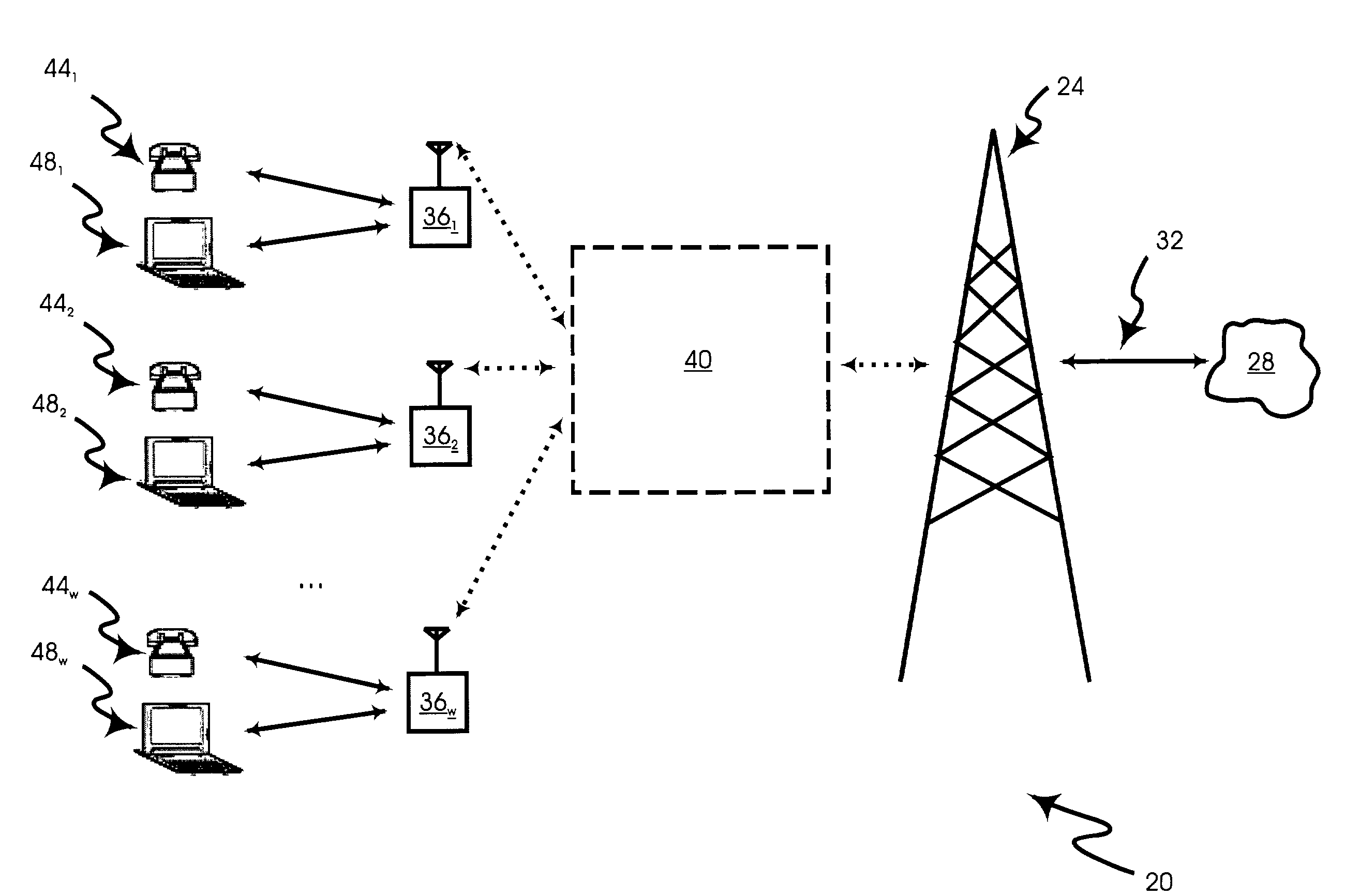
[0042]Referring now to FIG. 1, a wireless local loop system is indicated generally at 20. System 20 includes a wireless base station 24 that connects, through appropriate gateways (not shown), to a communication network 28 via a backhaul 32. Network 28 is typically the public switched telephone network (PSTN) combined with a packet switched data network, such as the Internet. Backhaul 32 can be any known type of backhaul link between wireless base station 24 and network 28, such as a T1, T3, OC1 or a wireless microwave link.

[0043]As will be explained in greater detail below, system 20 can have additional base stations 24, as desired, and that communications between multiple base stations 24 and subscriber stations 36 can be managed using known soft-handoff techniques. Additionally, base station 24 can be multi-sectored, each sector being defined by directional antennas, each sector comprising a different reception footprint.

[0044]A wireless link 40, composed of various communication...


PUM

PropertyMeasurementUnit
Angleaaaaaaaaaa
Lengthaaaaaaaaaa
Timeaaaaaaaaaa

Abstract

A wireless local loop system is provided that includes a wireless base station that communicates with a subscriber station via a wireless link. The wireless link can carry a voice service, such as telephone calls, or a data service, such as internet browsing. The subscriber station includes a steerable antenna. A presently preferred steerable antenna for use with the subscriber station includes a driven element mounted on a base plane that is surrounded by a plurality of parasitic elements also mounted to the base plane. The parasitic elements can be optionally grounded or floated in order to reflect the wireless link towards the driven element. The antenna can be oriented in a desired direction during the transception of a voice or data service. A method of transceiving between a wireless local loop subscriber station and a wireless local loop base station is also provided.

Description

FIELD OF THE INVENTION[0001]The present invention relates to telecommunication systems, and more specifically, the present invention relates to a steerable subscriber station antenna for a wireless local loop system.BACKGROUND OF THE INVENTION[0002]Various forms of modern wireless communications systems are well known. For example, cellular wireless voice services are now widely deployed in industrialized nations, and technology improvements are expected to enhance and expand cellular wireless services and lead to further deployment.[0003]Wireless local loop (WLL) systems are expected to become a viable alternative to the wired local loop telephone services offered by the existing local telephone companies throughout North America. WLL systems typically include a network of wireless base stations, each serving a plurality of subscribers. In turn, each subscriber possesses a subscriber station that supports voice services (e.g. telephone) and / or data services (e.g. internet) using wi...

Claims


Application Information

Patent Timeline
IPC IPC(8): H04Q7/20H04Q7/32C08L63/00C08L79/04H01L23/29H01Q1/22H01Q1/24H01Q3/24H01Q3/44H01Q21/28H04L12/56H04W84/14
CPCC08L63/00C08L79/04H04W84/14H01Q21/28H01Q3/446H01Q3/24H01L23/293H01Q1/241H01L2924/0002H01L2924/3011C08L2666/20H01L2924/00
Inventor BLODGETT, JAMES R.HEINZMANN, FRED JUDSON
Owner WI LAN INC
Learn More