
Perspective with shear warp

Inactive Publication Date: 2006-04-18
IBM CORP
View PDF7 Cites 5 Cited by
  • Summary
  • Abstract
  • Description
  • Claims
  • Application Information

AI Technical Summary

Benefits of technology

[0015]An advantage of the present invention is a method for generating a 2-D image with perspective using shear-warp factorization that uses one copy of the volume data.
[0016]A further advantage of the invention is the volume data may be accessed in storage order and which has the further advantage of accessing memory once for every slice.
[0017]In accordance with this invention there is provided a method for generating an 2-D projection directly from an 3-D volume data, the method comprising the steps of:
[0018](a) determining a viewing direction vector in a viewing frustum;
[0020](c) resampling the volume data in the direction of the major axis;

Problems solved by technology

Unfortunately, the application of volume rendering to medical imaging and scientific visualization is limited because it is computationally expensive to generate acceptable frame rates.
High quality images would take tens of seconds or even minutes to generate using typical workstation technology.
This approach is ineffective because many perceptual components of the image are obscured from the view of the user.
A more costly approach is to rely on special-purpose hardware, which drastically reduces the flexibility of the system.
These types of computers, however, are very expensive and require a large number of processors to achieve acceptable frame rates.
However, the current implementations of shear warp factorization are limited in several aspects.
It has been found that the stitching process is computationally not trivial and furthermore, some distortion is created along the border of the patches.
Additionally, using two or more factorizations is expensive in terms of memory access and computation.
Furthermore, current implementations also do not allow the observer to view the image from a position within the data set, a position, which can provide valuable information to the observer.

Method used


Image

  • Perspective with shear warp
  • Perspective with shear warp
  • Perspective with shear warp

Examples


Embodiment Construction

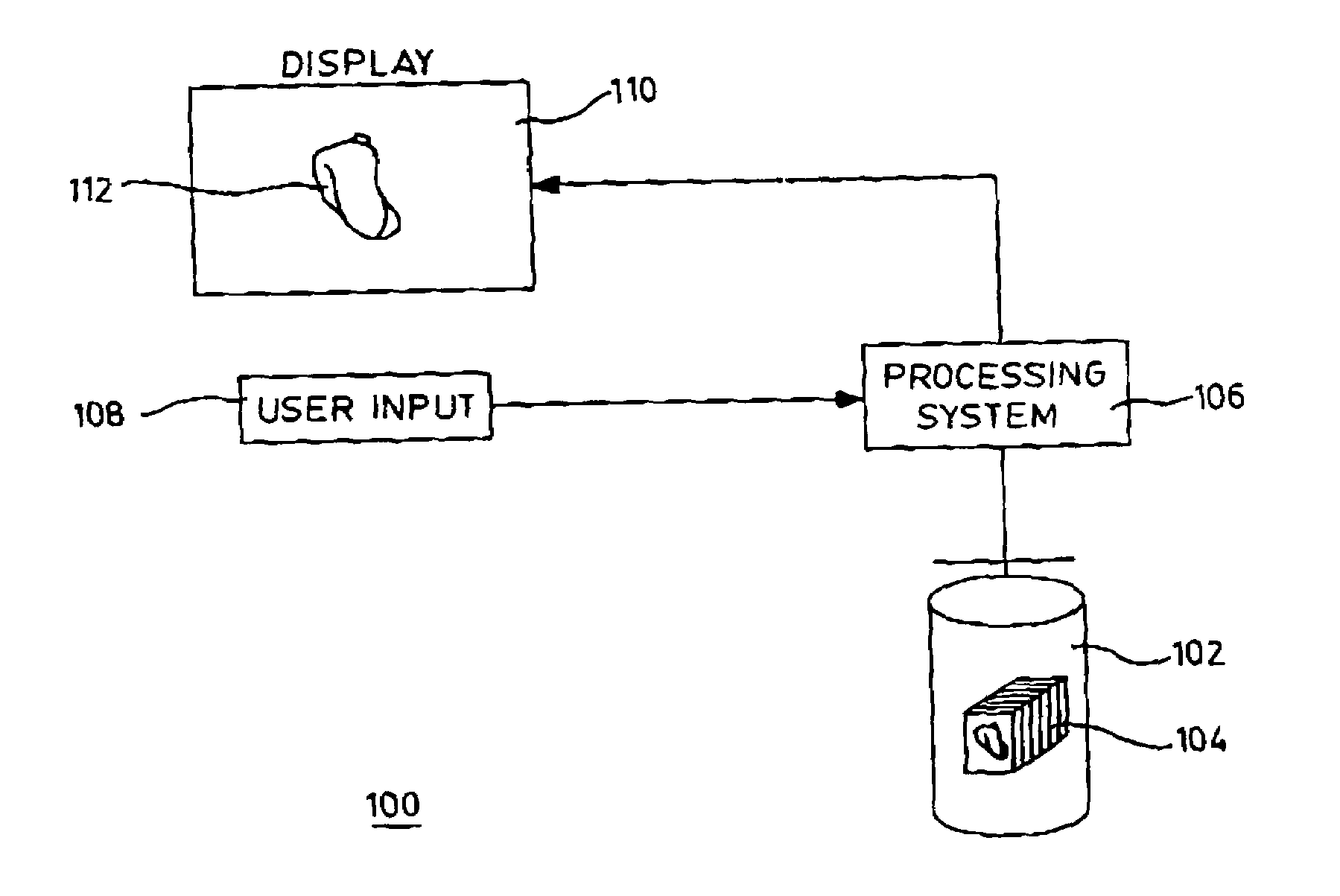
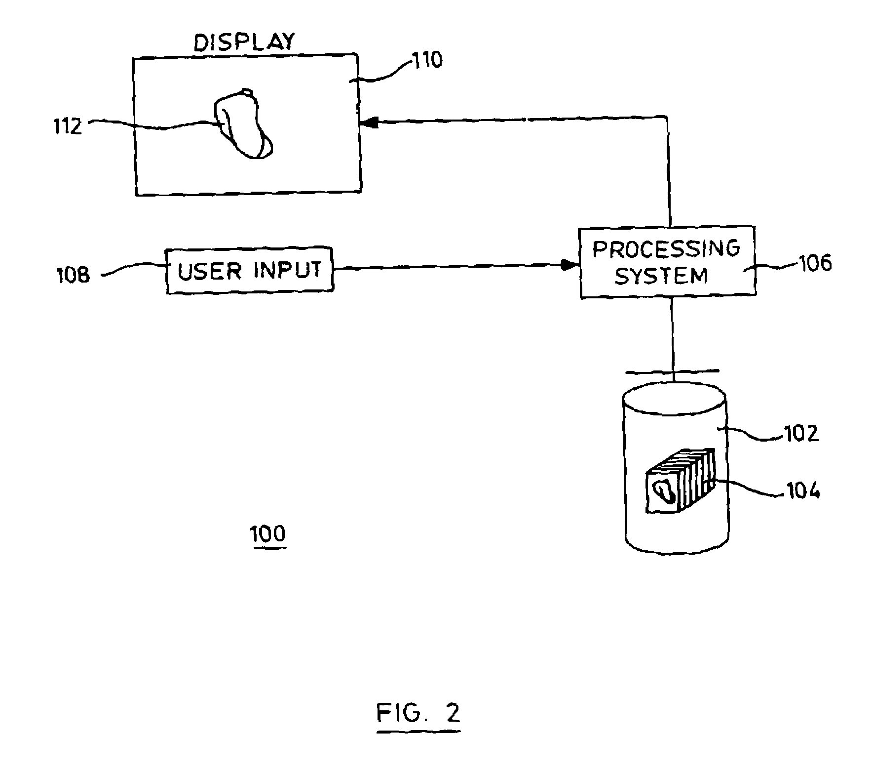
[0036]In the following description, like numerals refer to like structures in the drawings. Referring to FIG. 2, a block diagram of an imaging system for implementing an embodiment of the present invention is shown generally by numeral 100. The system 100 includes a memory 102 for storing a dataset 104 comprising a slice stack of the volume data, a processing system 106 responsive to a user input 108 for rendering and displaying on a display 110 a view 112 of the dataset 104.

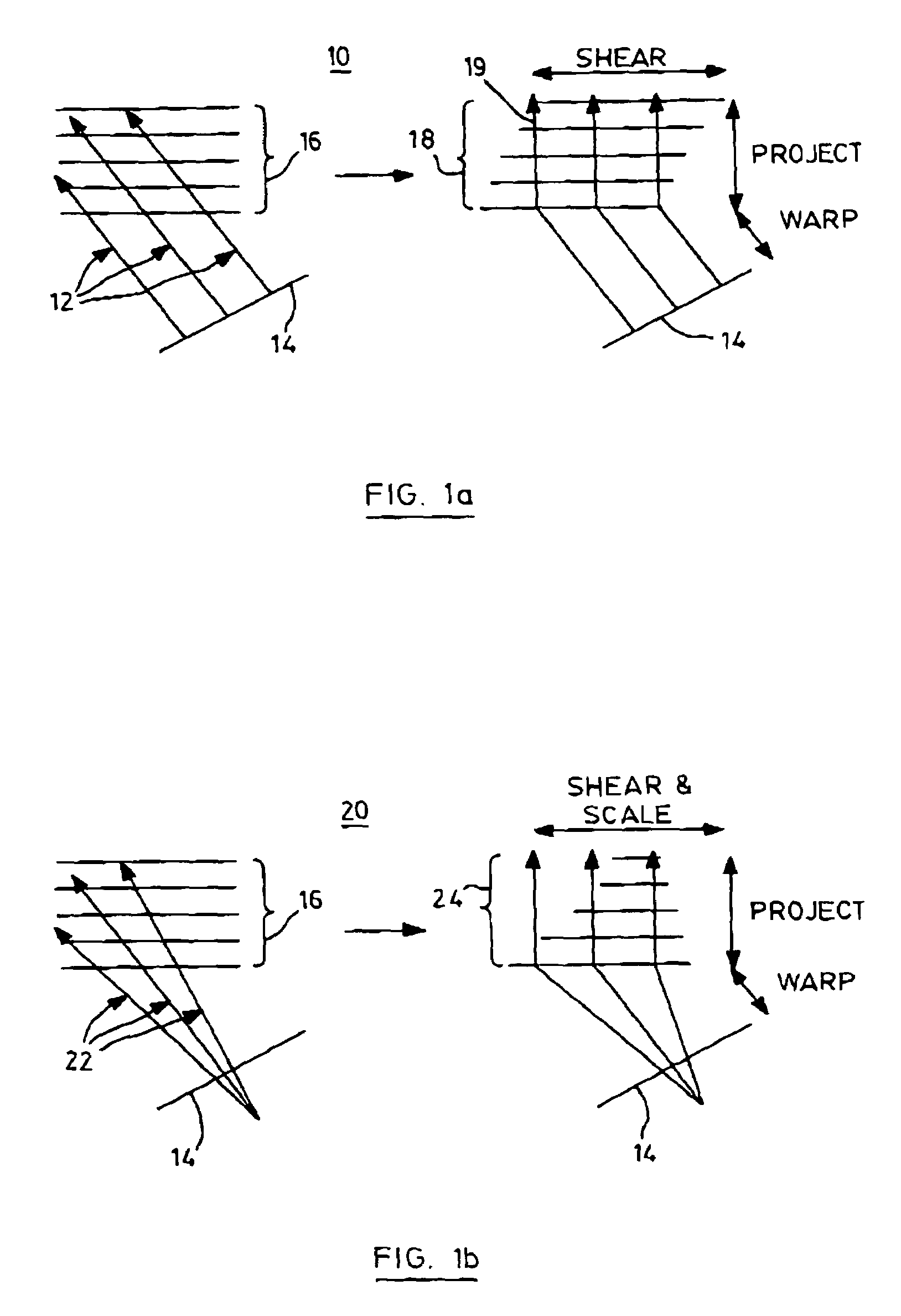
[0037]To reconstruct an image on the display in substantially realtime, in response to a user selected view of the dataset, the processing system performs a transformation by shear factorization To create a distorted image projection. Such distorted projection is not displayed. Before the volume is displayed, the projection undergoes a 2D geometric image warping operation to create a final 2D-image projection of the volume. Thus given a scene defined by a volume, a viewing position, a viewing direct ion and a vi...


PUM


Abstract

The present invention relates to a method for generating an 2-D projection directly from a 3-D volume data, the method comprising the steps of determining a viewing direction vector in a viewing frustum, determining a major axis of the direction vector, resampling the volume data in the direction of the major axis, applying a shear factorization to the resampled data; and rendering the factorized data. The method provides a singularly warped image which avoids have to patch images from multiple warp functions which, in turn, improves the quality of the final image. Finally, the image allows a scene to be rendered from within the scene itself. The invention can be applied to medical imaging and enable a surgeon to view an image such as a CT scan with perspective as well as from within the scan itself, providing the surgeon with an invaluable tool.

Description

[0001]This is a continuation of U.S. patent application Ser. No. 10 / 122,148 filed Apr. 15, 2002 now abandoned which is a continuation of PCT / CA00 / 01184 filed Oct. 13, 2000 which claims priority from Canadian Patent Application No. 2,286,447, filed Oct. 15, 1999.[0002]The present invention relates to the field of three-dimensional (3-D) image rendering, and more particularly to fast volume rendering using shear warp factorization.BACKGROUND OF THE INVENTION[0003]Real-time rendering of 3-D images in volume visualization applications has become increasingly important. This is particularly useful in clinical applications for the display and analysis of volumetric data sets acquired by imaging methods such as Computed Tomography (CT), Magnetic Resonance Imaging (MRI) or Ultrasonic imaging. Benefits of volume visualization include the ability to obtain oblique views for the increased understanding of complex geometric structures within organs, and the ability to measure volumes, areas, an...

Claims


Application Information

Patent Timeline
IPC IPC(8): G06K9/00G06T15/08
CPCG06T15/20G06T15/08
Inventor ACCOMAZZI, VITTORIO
Owner IBM CORP
Learn More