
Method, device and system for output impedance calibration that invariably maximizes hybrid performance

a technology of output impedance and hybrid performance, applied in the field of communication systems, can solve the problems of reducing the accuracy of transmit signal cancellation, incomplete cancellation, and certain drawbacks of hybrid system 100, and achieve the effect of minimizing the effects of on- and off-chip component imperfections and/or mismatches on hybrid performan

Inactive Publication Date: 2006-04-18
VINTOMIE NETWORKS +1
View PDF9 Cites 8 Cited by
  • Summary
  • Abstract
  • Description
  • Claims
  • Application Information

AI Technical Summary

Benefits of technology

The solution significantly reduces the impact of component mismatches, achieving optimal hybrid performance by automatically adjusting output impedance and bandwidth, maximizing gain and flexibility in system configuration while minimizing sensitivity to timing and component variations.

Problems solved by technology

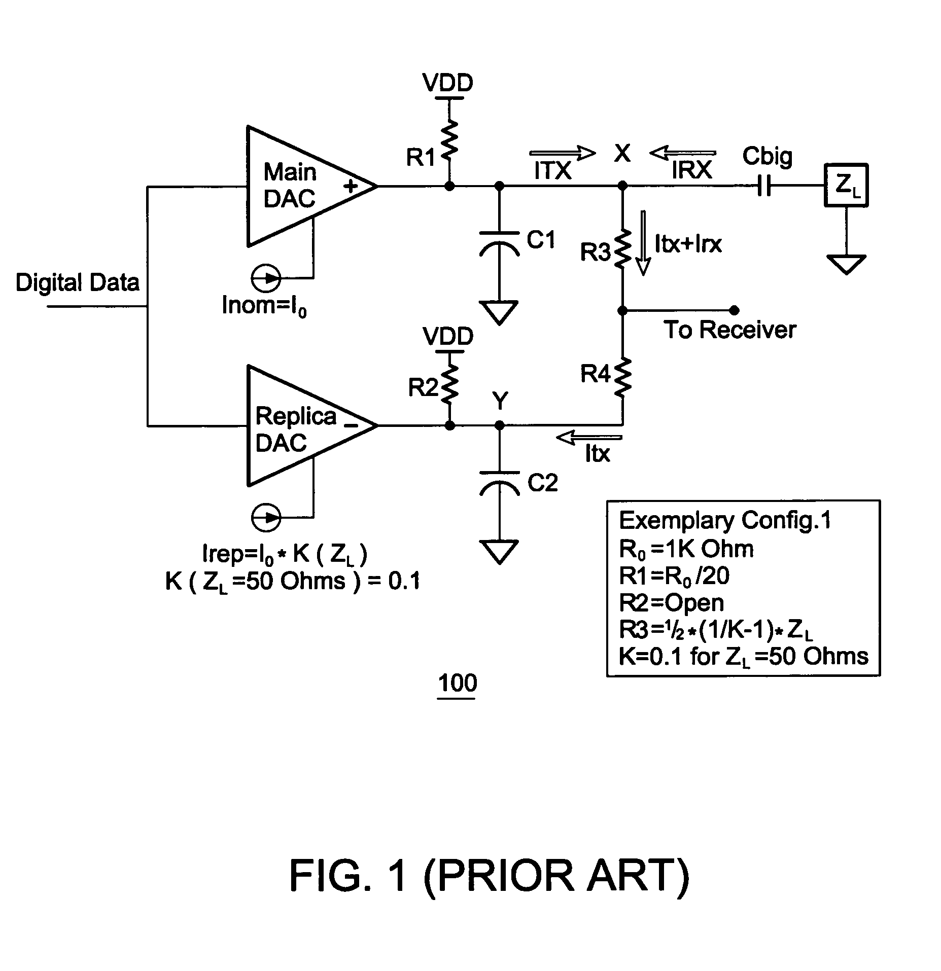
Without calibration, the hybrid system 100 suffers from certain drawbacks as well as performance limitations.
Most notably, the accuracy of the transmit signal cancellation is diminished by component mismatches, variations in the load impedance ZL, and variations in the on-chip component values.
More specifically, mismatches in absolute values between the off-chip load impedance ZL and the four on-chip resistors R1–R4 lead to incomplete cancellation of the transmit current Itx, which reduces effectiveness of the hybrid system 100.
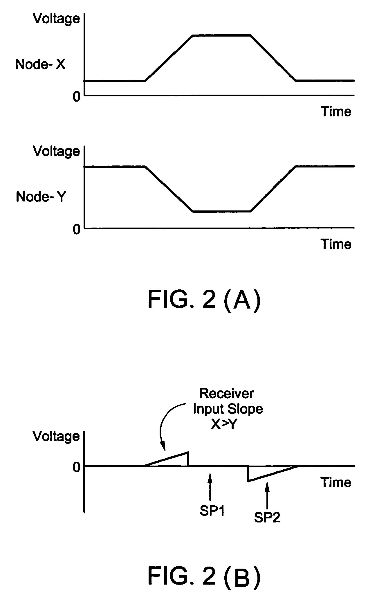
Similarly, mismatches in the frequency response at nodes X and Y lead to high frequency noise, which reduces the performance of the hybrid system 100.
However, the output impedance of the digital echo canceller is not calibrated, which means that its return loss is not properly controlled and which means that a poor return loss is likely to result.

Method used


Image

  • Method, device and system for output impedance calibration that invariably maximizes hybrid performance
  • Method, device and system for output impedance calibration that invariably maximizes hybrid performance
  • Method, device and system for output impedance calibration that invariably maximizes hybrid performance

Examples


Embodiment Construction

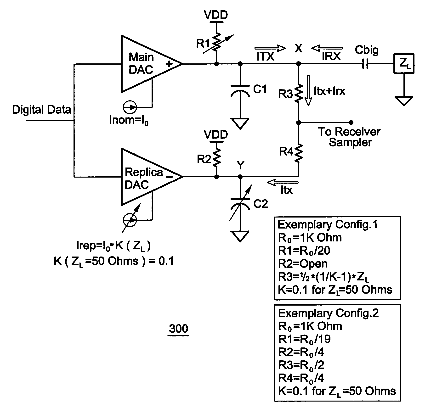
[0027]FIG. 3 shows an exemplary hybrid system 300 implementing the present invention. The hybrid system 300 has on- and off-chip components including an adjustable resistor R1 coupled to a Main DAC, an adjustable current source coupled to a Replica DAC, a resistor R2 coupled to the Replica DAC and a node Y, an adjustable capacitor C2 coupled to the node Y, a resistor R3 coupled to a node X and a Receiver, and a resistor R4 coupled to the Receiver and the node Y.

[0028]In addition to the adjustable capacitor C2, the hybrid system 300 further comprises a capacitor C1 coupled to the adjustable resistor R1 and the node X, and a capacitor Cbig coupled between the node X and a complex output impedance ZL representing the channel load.

[0029]According to the present invention, the hybrid system 300 not only minimizes the effects of mismatches between on- and off-chip components, but also minimizes the effect of bandwidth-mismatches between nodes. FIG. 2A graphically demonstrates a scenario i...


PUM


Abstract

A hybrid system with adjustable on-chip components and a method calibrating the same invariably maximizes hybrid performance despite of on- and off-chip component mismatches and imperfections. The hybrid system has a main DAC, a replica DAC, and three or four resistors. Both DACs are directly connected to digital data. An adjustable resistor is connected to the main DAC and is calibrated such that output impedance is automatically adjusted to match an off-chip load impedance Z. A replica DAC current K is calibrated for optimum DC matching in presence of Z. An adjustable capacitor C2 is calibrated for slope-matching (bandwidth matching). If Z changes, the calibration procedure should be repeated for optimal performance. These three calibration mechanisms can be utilized individually or in combination. The present invention is compatible with both analog and digital echo-cancellers.

Description

CROSS-REFERENCES TO RELATED APPLICATIONS[0001]This application claims the benefit of a provisional Patent Application No. 60 / 506,472, filed Set. 26, 2003, which is incorporated herein by reference in its entirety.BACKGROUND OF THE INVENTION[0002]1. Field of the Invention[0003]This invention relates generally to communication systems. More particularly, it relates to an output impedance method calibrating a hybrid local-echo canceller and a hybrid structure implementing the same. An implementation of the invention is also compatible with a mixed-signal echo canceller.[0004]2. Description of the Related Art[0005]A hybrid generally refers to a device that converts a bi-directional path into two separate unidirectional paths for transmit and receive. In full-duplex communication systems, a hybrid local-echo canceller is typically used to separate incoming receive signals from outgoing transmit signals.[0006]FIG. 1 shows a Pam-4 current-mode hybrid system 100 comprising two digital-to-an...

Claims


Application Information

Patent Timeline
Patent Type & Authority Patents(United States)
IPC IPC(8): H04M7/04H03H7/40H03M1/06H03M1/10H03M1/66H04L5/14
CPCH03H7/40H04L5/1423H03M1/1009H03M1/0678H04L25/0278H03M1/66
Inventor DYER, KENNETH C.TAKATORI, HIROSHI
Owner VINTOMIE NETWORKS
Learn More