
Spray gun with improved pre-atomization fluid mixing and breakup

a pre-atomization fluid and spray gun technology, applied in the field of spray coating systems, can solve the problems of inability to break up the foregoing particulate/ligament, undesired consistency of spray coating, and existing spray coating devices such as air atomizing spray guns, so as to facilitate improve the atomization of spray coating devices, and enhance the effect of fluid mixing and fluid breakup

Inactive Publication Date: 2006-04-18
CARLISLE FLUID TECH INC
View PDF26 Cites 25 Cited by
  • Summary
  • Abstract
  • Description
  • Claims
  • Application Information

AI Technical Summary

Benefits of technology

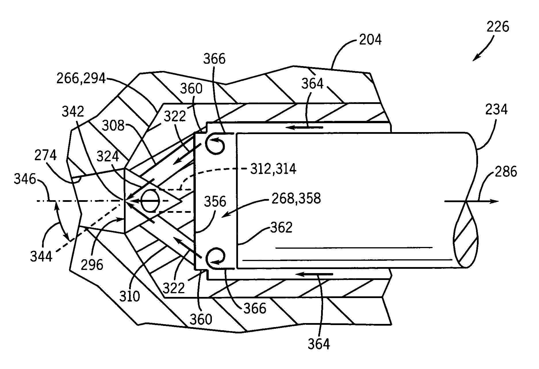
[0005]The present technique provides a system and method for improving atomization in a spray coating device by internally mixing and breaking up a desired coating fluid prior to atomization at a spray formation section of the spray coating device. An exemplary spray coating device of the present technique has a mixture-inducing valve disposed adjacent a flow barrier upstream of a spray formation exit. The mixture-inducing valve may have a variety of blunt / angled structures and internal passages to facilitate fluid mixing. The mixture-inducing valve also may interact with the flow barrier to enhance the fluid mixing and fluid breakup. One embodiment of the present spray coating device has an internal fluid breakup section, such as an impinging jet section, adjacent the mixture-inducing valve. The resulting spray coating has refined characteristics, such as reduced mottling.

Problems solved by technology

Existing spray coating devices, such as air atomizing spray guns, are often unable to breakup the foregoing particulate / ligaments.
The resulting spray coating has an undesirably inconsistent appearance, which may be characterized by mottling and various other inconsistencies in textures, colors, and overall appearance.

Method used


Image

  • Spray gun with improved pre-atomization fluid mixing and breakup
  • Spray gun with improved pre-atomization fluid mixing and breakup
  • Spray gun with improved pre-atomization fluid mixing and breakup

Examples


Embodiment Construction

[0024]As discussed in detail below, the present technique provides a refined spray for coating and other spray applications by internally mixing and breaking up the fluid within the spray coating device. This internal mixing and breakup is achieved by passing the fluid through one or more varying geometry passages, which may comprises sharp turns, abrupt expansions or contractions, or other mixture-inducing flow paths. For example, the present technique may flow the fluid through or around a modified needle valve, which has one or more blunt or angled edges, internal flow passages, and varying geometry structures. Moreover, the present technique may provide a flow barrier, such as a blockade in the fluid passage, having one or more restricted passages extending therethrough to facilitate fluid mixing and particulate breakup. For example, the flow barrier may induce fluid mixing in a mixing cavity between the flow barrier and the modified needle valve. The flow barrier also may creat...


PUM


Abstract

The present technique provides a system and method for improving atomization in a spray coating device by internally mixing and breaking up a desired coating fluid prior to atomization at a spray formation section of the spray coating device. An exemplary spray coating device of the present technique has a mixture-inducing valve disposed adjacent a flow barrier upstream of a spray formation exit. The mixture-inducing valve may have a variety of blunt / angled structures and internal passages to facilitate fluid mixing. The mixture-inducing valve also may interact with the flow barrier to enhance the fluid mixing and fluid breakup. One embodiment of the present spray coating device has an internal fluid breakup section, such as an impinging jet section, adjacent the mixture-inducing valve. The resulting spray coating has refined characteristics, such as reduced mottling.

Description

CROSS REFERENCE TO RELATED APPLICATIONS[0001]This is a continuation of application Ser. No. 10 / 223,193 filed on Aug. 19, 2002 now U.S. Pat. No. 6,808,122.BACKGROUND OF THE INVENTION[0002]The present technique relates generally to spray systems and, more particularly, to industrial spray coating systems. The present technique specifically provides a system and method for improving atomization in a spray coating device by internally mixing and breaking up the fluid prior to atomization at a spray formation section of the spray coating device.[0003]Spray coating devices are used to apply a spray coating to a wide variety of produce types and materials, such as wood and metal. The spray coating fluids used for each different industrial application may have much different fluid characteristics and desired coating properties. For example, wood coating fluids / stains are generally viscous fluids, which may have significant particulate / ligaments throughout the fluid / stain. Existing spray coa...

Claims


Application Information

Patent Timeline
Patent Type & Authority Patents(United States)
IPC IPC(8): B05B17/04B05B7/04B05B7/06B05B1/30B05B1/34B05B7/12B05C7/04
CPCB05B1/34B05B1/3046B05B7/1209B05C7/04
Inventor MICHELI, PAUL R.
Owner CARLISLE FLUID TECH INC
Learn More