
Box-like cooling system

Inactive Publication Date: 2006-04-18
MODINE MFG CO
View PDF20 Cites 8 Cited by
  • Summary
  • Abstract
  • Description
  • Claims
  • Application Information

AI Technical Summary

Benefits of technology

[0006]The principle object of the invention is to

Problems solved by technology

This requires additional space over the top of the box-like cooling system.
This can create a problem in modern designs of utility vehicles and trucks because the cooling system may require space that could otherwise be provided for the interior of the vehicle to enhance the comfort of the operating personnel.
However, in conventional systems that utilize axial fans, the desired cooling power will typical require increasing the surface area of the cooling system through which the air is flowed beyond what may be available in the typical utility vehicle without altering the vehicle concept.

Method used


Image

  • Box-like cooling system
  • Box-like cooling system
  • Box-like cooling system

Examples


Embodiment Construction

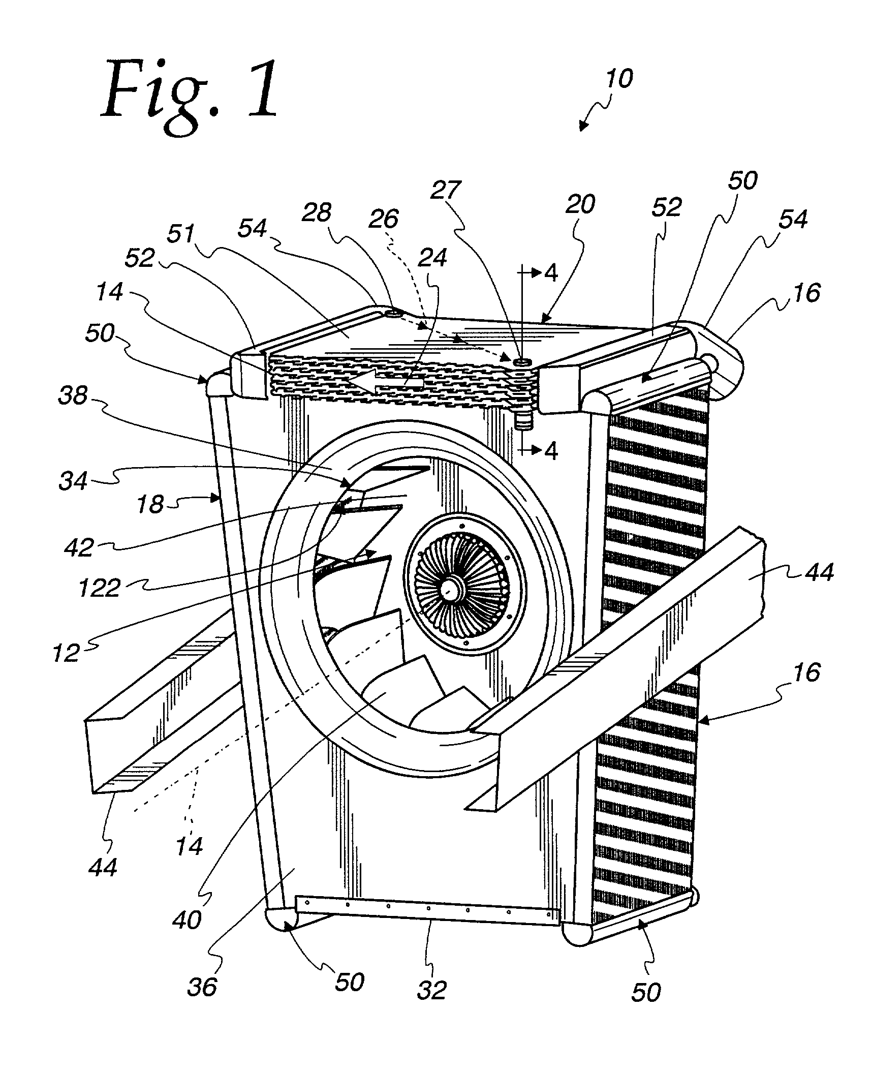
[0023]With reference to FIGS. 1 and 2, a cooling system 10 embodying the present invention includes a radial fan 12 rotatable about an axis 14 to deliver a radial air flow to the cooling system 10, a plurality of heat exchangers 16, 18, and 20 spaced radially from the fan 12 and arranged around the fan 12 in a box-like configuration to receive the radial air flow therefrom, with the heat exchangers 16, 18, and 20 bounding an interior space 22 (as best seen in FIG. 6) of the cooling system 10. The heat exchanger 20 is provided in the form of a charge air cooler 20 that includes a first flow path, shown schematically at 24 in FIG. 1, for a charge air flow in heat exchange relation with a second flow path, shown schematically at 26, for an engine coolant flow of the vehicle. As best seen in FIG. 3, the cooling system 10 further includes a surface 30 associated with the charge air cooler 20 to substantially block the radial airflow from exiting the interior space 22 through the charge a...


PUM


Abstract

A cooling system includes a radial fan rotatable by an axis to deliver radial air flow to the cooling system, a plurality of heat exchangers spaced radially from the fan and arranged around the fan in a box-like configuration to receive the radial air flow therefrom, with the heat exchangers bounding an interior space of the cooling system. One of the heat exchangers is provided in the form of a charge air cooler that includes a first flow path for a charge air flow in heat exchange relation with a second flow path for an engine coolant flow of the vehicle. The cooling system further includes a surface associated with the charge air cooler to substantially block the radial air flow from exiting the interior space through the charge air cooler.

Description

RELATED APPLICATIONS[0001]This application claims priority to prior filed German application DE 101 20 483.3 filed Apr. 25, 2001, the entire disclosure which is incorporated herein by reference.FIELD OF THE INVENTION[0002]This invention relates to cooling systems, and more particularly to cooling systems wherein a box-like arrangement of heat exchangers surrounds a radial fan to receive a radial air flow therefrom.BACKGROUND OF THE INVENTION[0003]Box-like cooling systems are known for use in vehicles, particular in utility vehicles or trucks. In principle, such cooling systems are more efficient then conventional cooling systems that utilize an axial fan because the radial fans utilized in box-like cooling systems can provide a greater air flow volume then axial fans and have better running properties. Examples of box-like cooling systems are shown in EP 1 045 217 A1 and DE 197 24 728 A1.[0004]In at least some box-like cooling systems, such as is shown in DE 197 24 728 A1, a charge ...

Claims


Application Information

Patent Timeline
IPC IPC(8): B60H3/00F01P3/18F01P11/10F02B29/04F28D1/04
CPCF01P3/18F01P11/10F02B29/0462F28D1/0426F02B29/0475F01P2003/182Y02T10/146F28D2021/0082F28D2021/0094F02B29/0431Y02T10/12
Inventor FISCHER, DANIELAKNECHTZOBEL, WERNERREICHLER, MARKSOLDNER, JORG
Owner MODINE MFG CO
Learn More