
Pilot oil ignition gas engine and method of operating pilot oil ignition gas engine

a technology of pilot oil ignition and gas engine, which is applied in the direction of electric control, machines/engines, mechanical equipment, etc., can solve the problems of engine failure to activate (stall), uncombusted gas released into the exhaust, and danger of sudden combustion in the exhaust pip

Inactive Publication Date: 2006-04-18
NIIGATA POWER SYST CO LTD
View PDF8 Cites 1 Cited by
  • Summary
  • Abstract
  • Description
  • Claims
  • Application Information

AI Technical Summary

Benefits of technology

[0008]Therefore, in a system using a gas engine, it is important to reduce misfire at the time of activation.

Problems solved by technology

However, a pilot ignition oil type gas engine is also ignited by a spark plug or the like, since compression ignition is difficult at the time of activating in a low-temperature combustion chamber.
When misfire is generated during the activation, uncombusted gas is released into the exhaust.
When the ratio of generated misfire increases, so does the density of combustion gas in the exhaust pipe, and, when the gas density reaches a flammable range, there is a danger of sudden combustion in the exhaust pipe.
Furthermore, when the ratio of misfire increases, the engine may fail to activate (stall).

Method used


Image

  • Pilot oil ignition gas engine and method of operating pilot oil ignition gas engine
  • Pilot oil ignition gas engine and method of operating pilot oil ignition gas engine
  • Pilot oil ignition gas engine and method of operating pilot oil ignition gas engine

Examples


Embodiment Construction

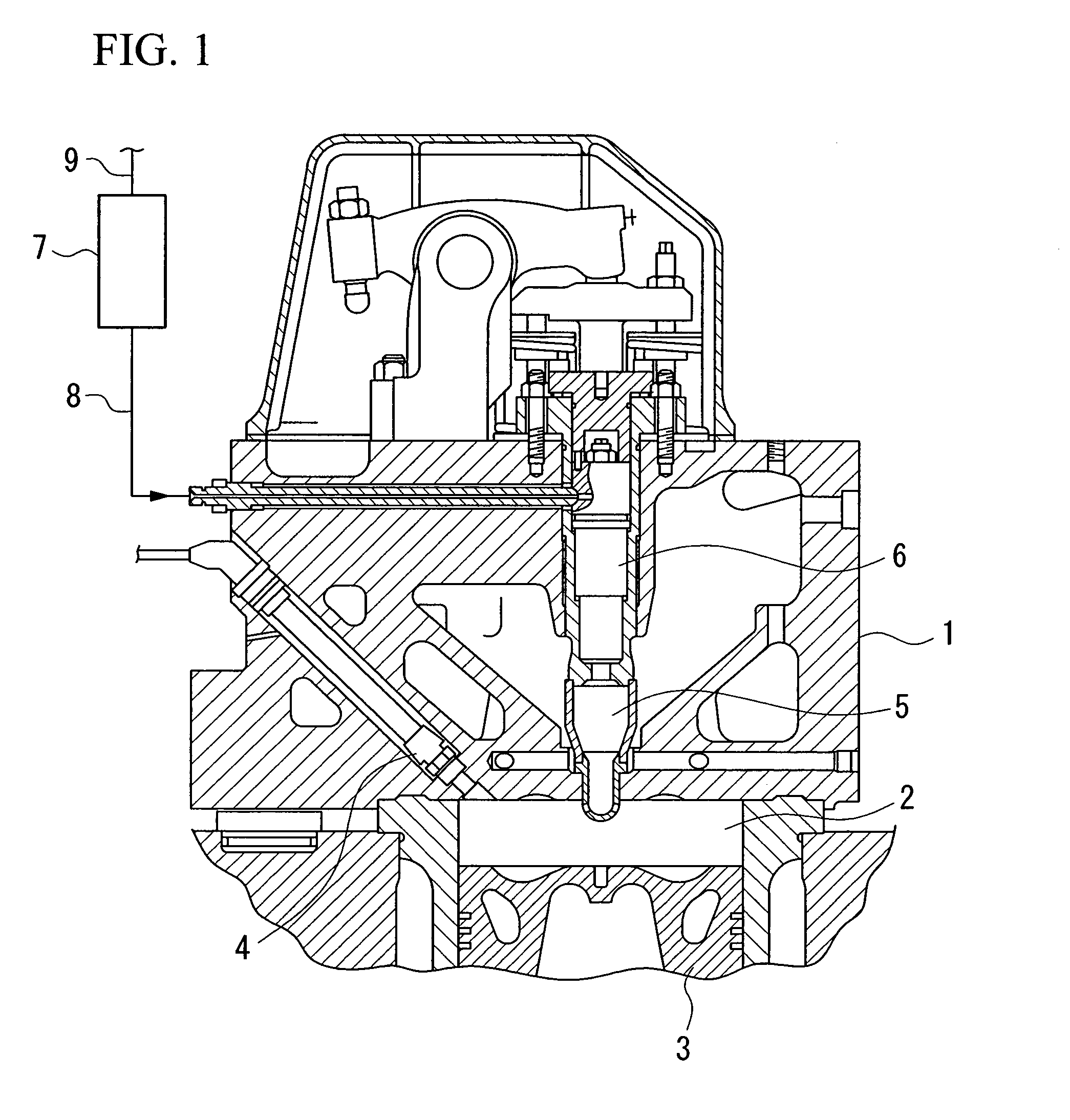
[0024]A first example of a preferred embodiment of the present invention will be explained with reference to FIGS. 1 to 4.

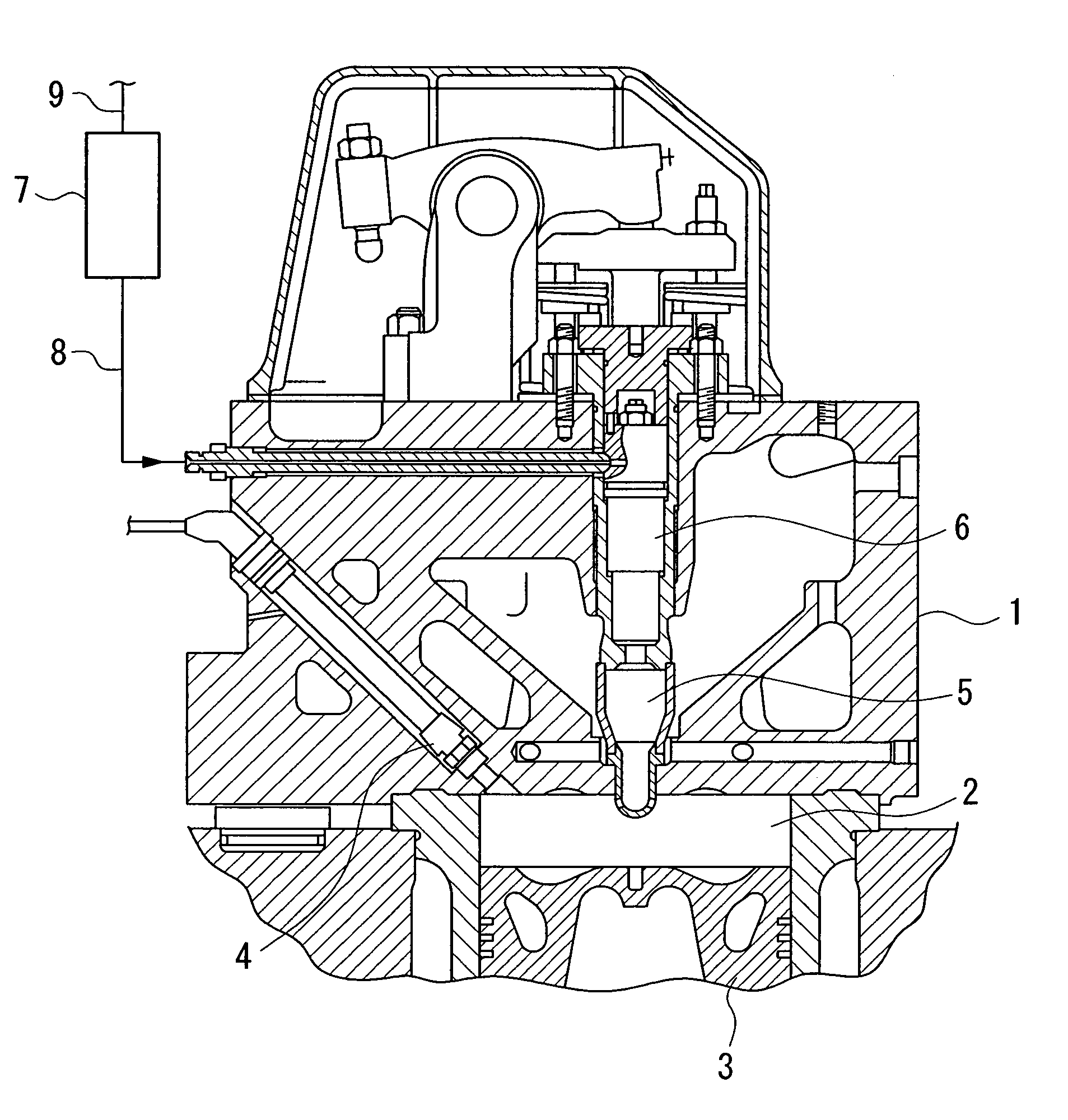
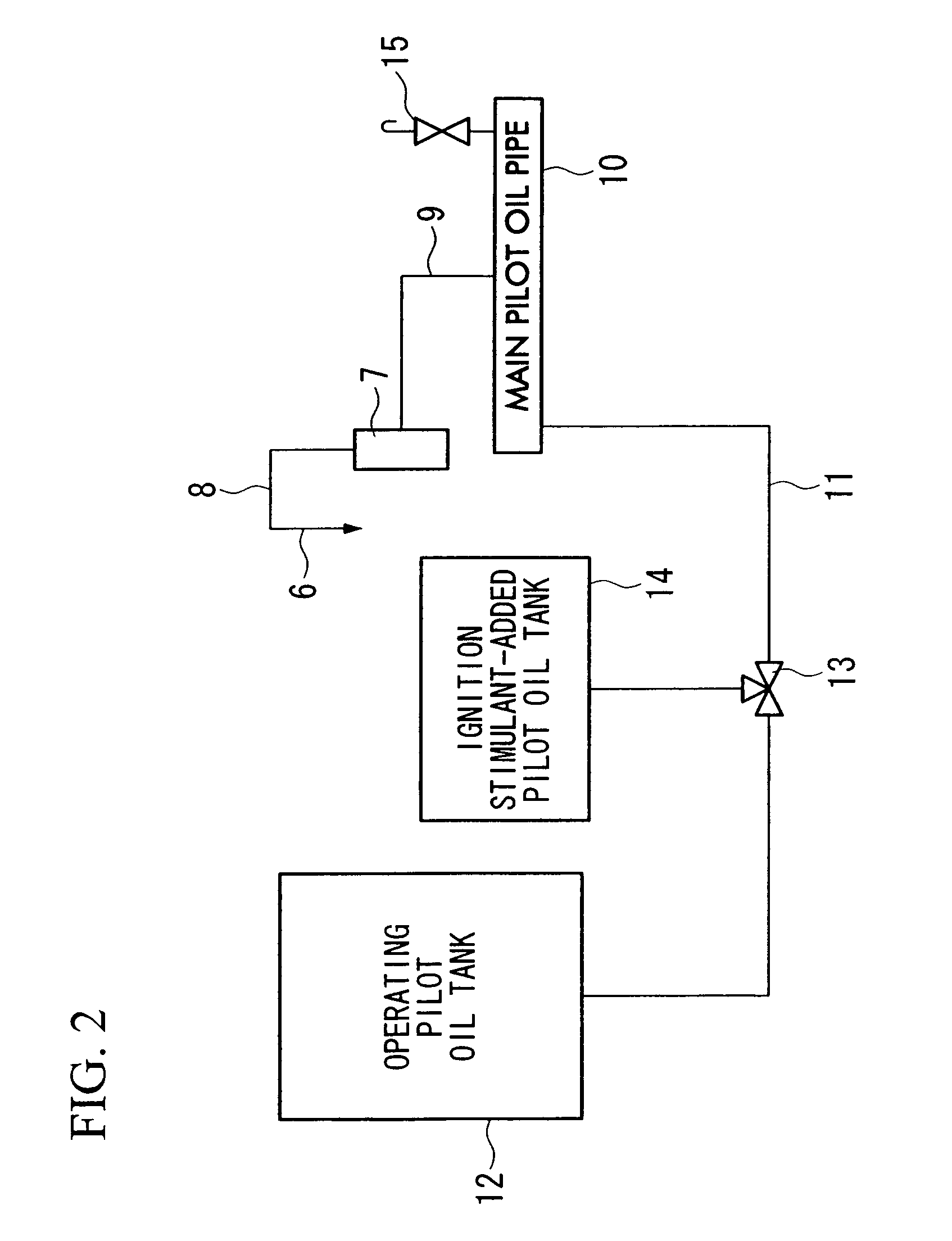
[0025]The constitution of the components around the main combustion chamber of the gas chamber in this example is the same as that shown in FIG. 1. That is, in a cylinder head 1, a preparatory combustion chamber 5 leads to a main combustion chamber 2 in which a piston 3 rises and falls, and a pilot oil fuel valve 6 is provided inside the preparatory combustion chamber 5. The pilot oil fuel valve 6 is connected via a first pipe 8 to a pilot oil pump 7, which is driven by the driving force of the gas engine. Furthermore, as shown in FIG. 2, the pilot oil pump 7 is connected via a second pipe 9 to a pilot oil main valve 10.

[0026]FIGS. 1 and 2 show only one pair comprising the pilot oil fuel valve 6 and the pilot oil pump 7, but since the gas engine of this example has multiple cylinders, the pilot oil fuel valve 6, the pilot oil pump 7, and the first and second pipe...


PUM


Abstract

The gas engine of the present invention has a pilot oil fuel valve, a pilot oil pump, and first and second pipes connected to a pilot oil main pipe, for each of a plurality of combustion chambers. An operating pilot oil tank and an ignition stimulant-added pilot oil tank are connected via a switching valve to a third pipe, connected to an end of the pilot oil main pipe. Before operating stops, the pilot oil is discharged by opening an exhaust valve, and thereafter, the switching valve is switched and pilot oil which the ignition stimulant has been added to is supplied into the pipe. Consequently, the pilot oil downstream from the main pipe is replaced with the pilot oil which the ignition stimulant has been added to. Therefore, at the time of the next activation, pilot oil which the ignition stimulant has been added to is sprayed from the fuel valve, and, as a result, misfire at the time of activation is reduced, and a highly reliable engine is obtained.

Description

BACKGROUND OF INVENTION[0001]1. Field of the Invention[0002]The present invention relates to a structure of a gas engine for reducing the ratio of misfire generated at the time of activating a pilot oil ignition type gas engine, and increasing the activation stability, and also relates to an operating method of the gas engine.[0003]2. Description of Related Art[0004]Since pilot ignition type gas engines, which perform compression ignition, have higher ignition energy than conventional spark plug ignition type gas engines, they can achieve a far greater increase in output. However, a pilot ignition oil type gas engine is also ignited by a spark plug or the like, since compression ignition is difficult at the time of activating in a low-temperature combustion chamber. Therefore, to make the engine more economical by reducing the number of its components, or to achieve smoother activation, there is a need to adjust conditions so as to enable earlier compression ignition and realize pil...

Claims


Application Information

Patent Timeline
Patent Type & Authority Patents(United States)
IPC IPC(8): F02B3/00F02D19/10F02D41/00F02D41/04F02M43/00
CPCF02D19/10F02D41/0027F02M43/00F02D19/061Y02T10/36F02D41/042Y02T10/30F02D19/02
Inventor GOTO, SATORUNISHI, YOSHIFUMI
Owner NIIGATA POWER SYST CO LTD
Learn More