
System and method for monitoring performance of downhole equipment using fiber optic based sensors

a technology of fiber optic based sensors and equipment, applied in the field of system and method for monitoring the performance of downhole equipment, can solve the problems of unscheduled downtime, high repair cost, and potential damage to neighboring equipmen

Active Publication Date: 2006-04-18
WEATHERFORD TECH HLDG LLC
View PDF20 Cites 73 Cited by
  • Summary
  • Abstract
  • Description
  • Claims
  • Application Information

AI Technical Summary

Benefits of technology

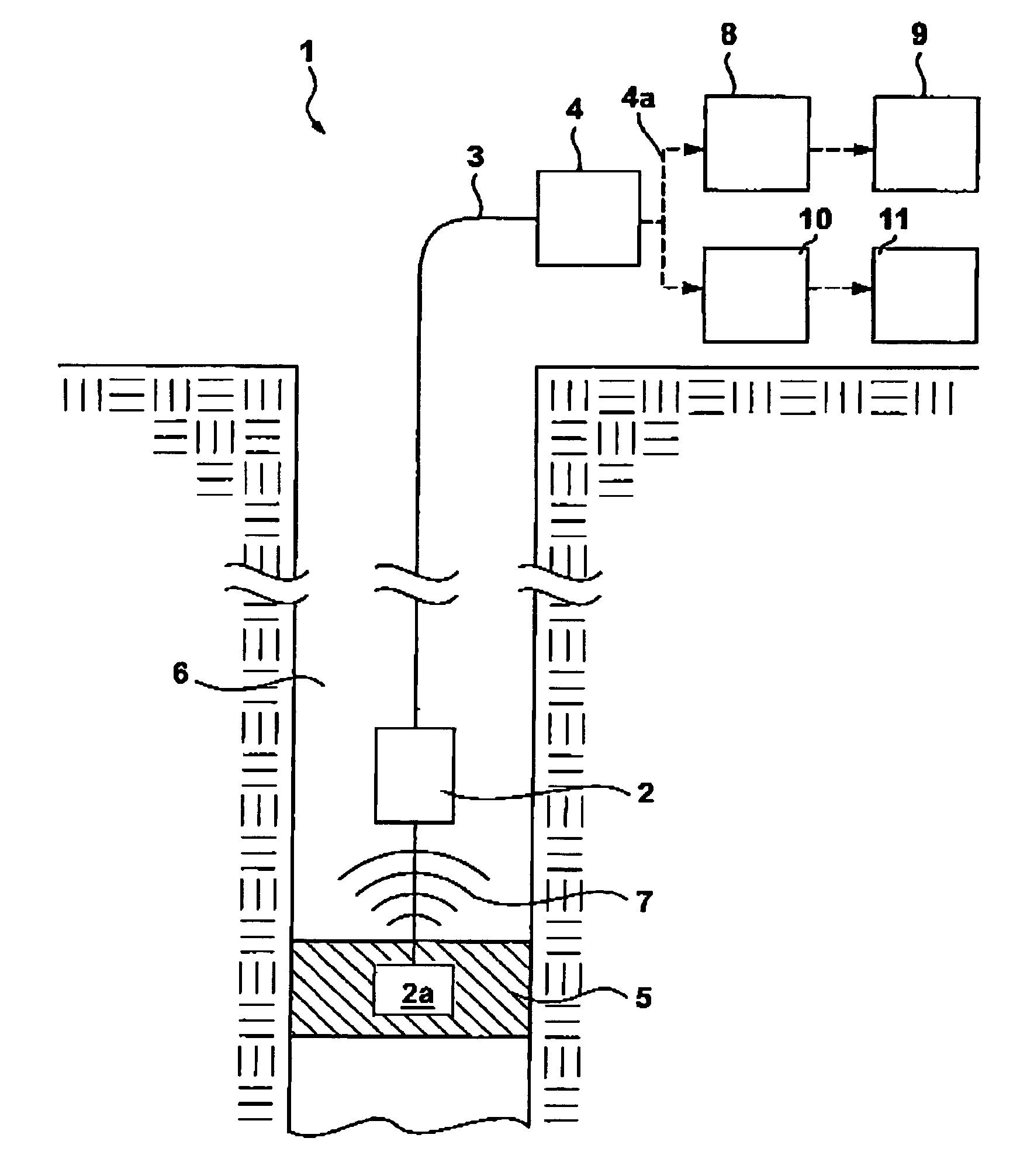
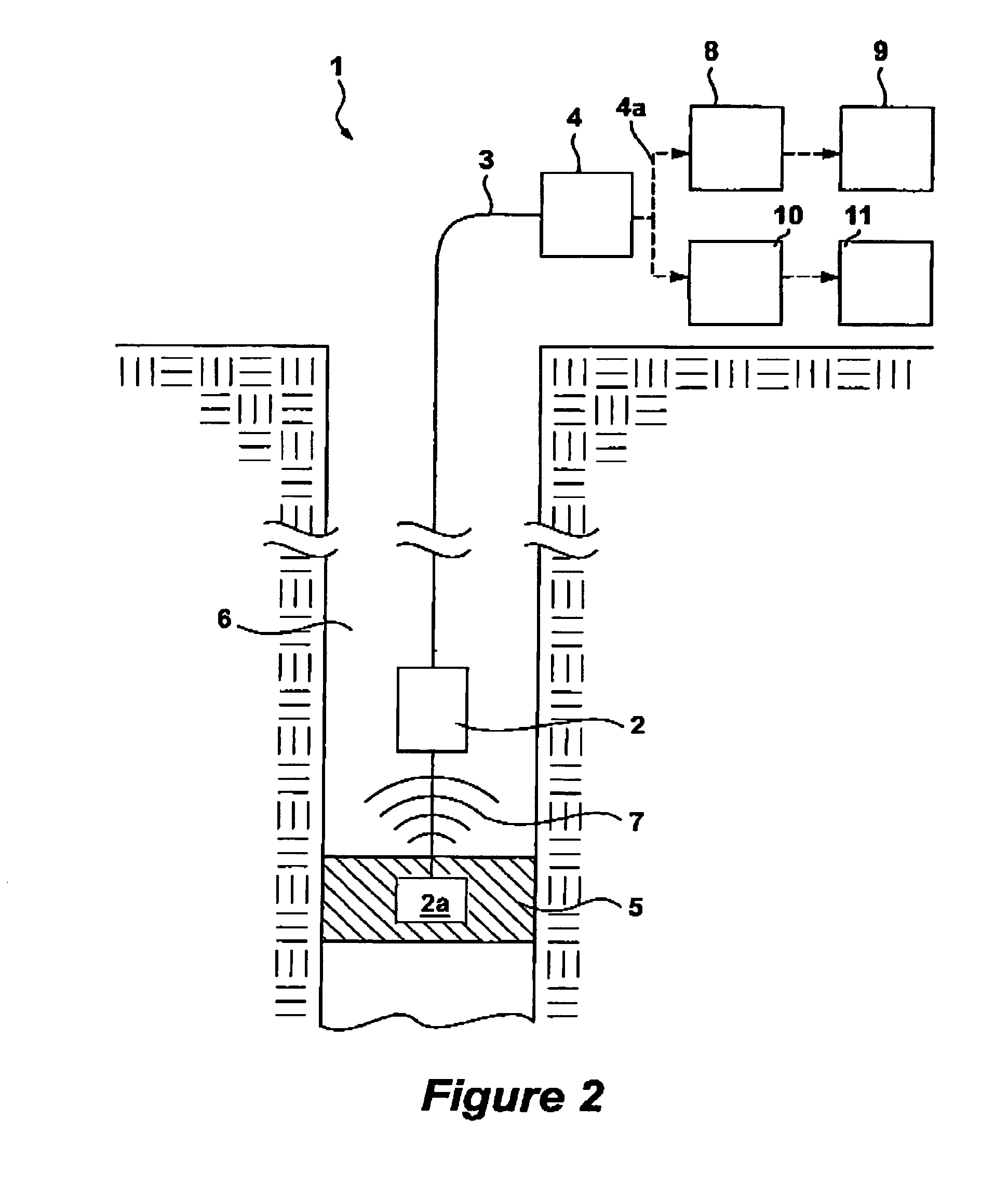
[0008]A method and system for monitoring the operation of downhole equipment, such as electrical submersible pumps, is disclosed. The method and system rely on the use of coiled fiber optic sensors, such as hydrophones, accelerometers, and / or flow meters. These sensors are either coupled to or placed in proximity to the equipment being monitored. As the sensor is perturbed by acoustic pressure disturbances emitted from the equipment, the length of the sensing coil changes, enabling the creation of a pressure versus time signal. This signal is converted into a frequency spectrum indicative of the acoustics emissions of the equipment, which can then be manually or automatedly monitored to see if the equipment is functioning normally or abnormally, and which allows the operator to take necessary corrective actions.

Problems solved by technology

Failure of equipment placed downhole in an oil / gas well results in unscheduled downtime, lost production, high repair costs, and potential damage to neighboring equipment.
Common failure modes of downhole equipment include excessive wear, failure of bearings, dynamic stress, excessive fouling, and impeller damage.
Unfortunately, downhole equipment is typically inaccessible during operation, and if a failure occurs there is often no indication of what component has failed.
However, because these systems rely on electronic components, they are susceptible to failure in the harsh downhole environment, which is characterized by extreme pressures, temperatures, and caustic chemicals.
However, a review of this patent reveals a rather complicated sensor structure, as various schemes and components must be used in the sensor housing to allow each of the FBGs to detect the parameter of interest.
Although the disclosure in the '911 patent is rather vague, it is reasonable to conclude that these prior art fiber optic based approaches to monitoring downhole equipment operation present complicated approaches.
Moreover, the '860 patent only contemplates a direct connection of the sensors to the equipment being measured, which may be unsuitable for applications in which the equipment will not lend itself to such modification.

Method used


Image

  • System and method for monitoring performance of downhole equipment using fiber optic based sensors
  • System and method for monitoring performance of downhole equipment using fiber optic based sensors
  • System and method for monitoring performance of downhole equipment using fiber optic based sensors

Examples


Embodiment Construction

[0014]A preferred embodiment for detecting the operational efficiency of downhole equipment utilizes a fiber optic based hydrophone having a sensitive coil of fiber optic cable to measure the acoustic emissions of the equipment. Such sensors preferably utilize fiber Bragg gratings (FBGs) and can measure acoustic signals in a frequency range up to 50 kHz. More generally, a sensor useable with the disclosed equipment-monitoring technique includes any types of fiber optic sensor employing a sensing coil of fiber optic cable, such as the accelerometers or flow meters disclosed and incorporated herein.

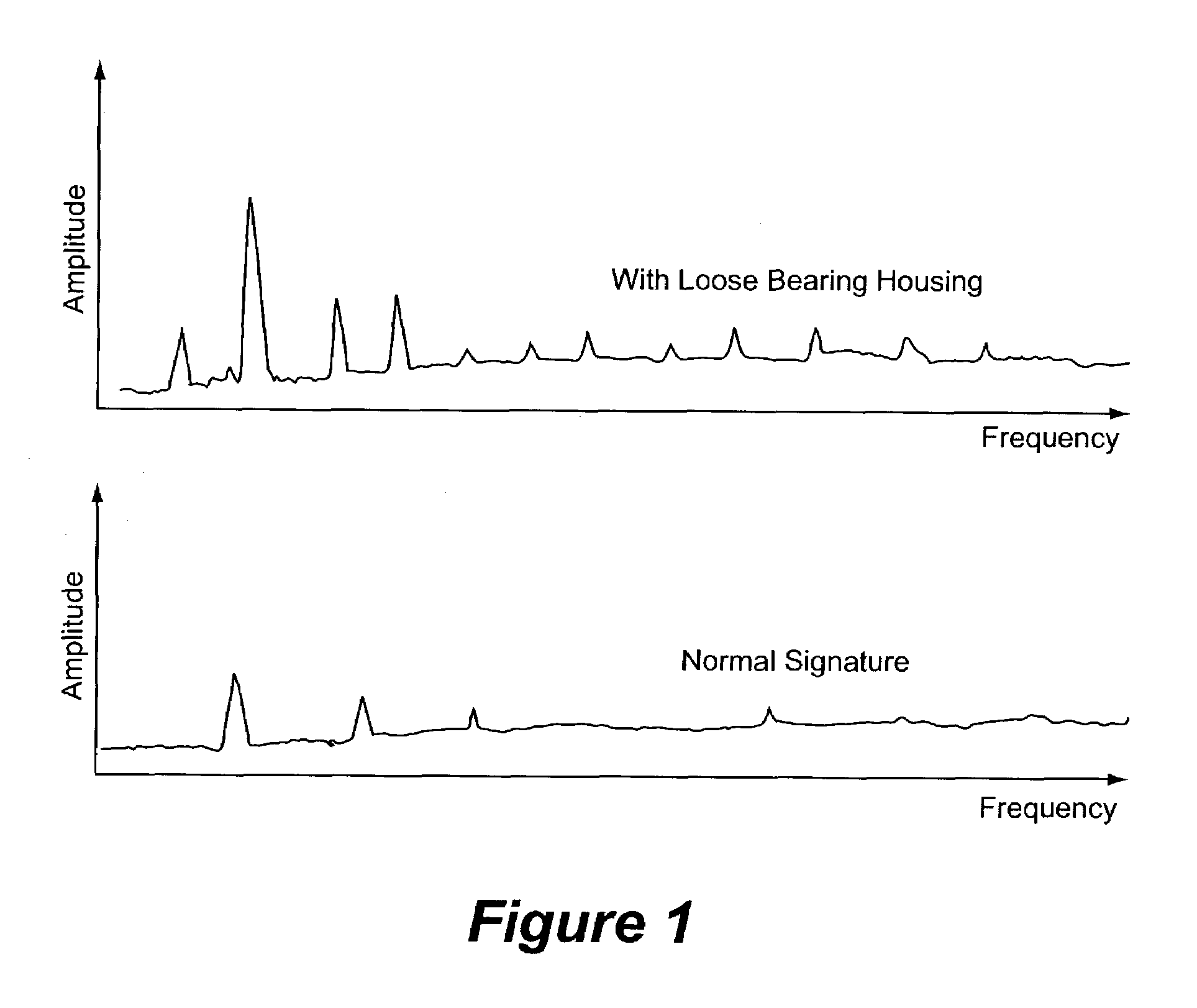
[0015]FIG. 1 generally illustrates the utility of and need for equipment monitoring. In FIG. 1, two audio spectra are disclosed for an Electrical Submersible Pump (ESP). The bottom spectrum shows the spectra emitted by an ESP that is functioning properly. As can be seen, this spectrum contains certain resonant peaks that are caused by naturally occurring phenomenon in the pump, and may be c...


PUM


Abstract

A method and system for monitoring the operation of downhole equipment, such as electrical submersible pumps, is disclosed. The method and system rely on the use of coiled fiber optic sensors, such as hydrophones, accelerometers, and / or flow meters. These sensors are either coupled to or placed in proximity to the equipment being monitored. As the sensor is perturbed by acoustic pressure disturbances emitted from the equipment, the length of the sensing coil changes, enabling the creation of a pressure versus time signal. This signal is converted into a frequency spectrum indicative of the acoustics emissions of the equipment, which can then be manually or automatedly monitored to see if the equipment is functioning normally or abnormally, and which allows the operator to take necessary corrective actions.

Description

FIELD OF THE INVENTION[0001]The present invention relates generally to a system and method for monitoring performance of downhole equipment and, more particularly to a system and method for monitoring changes in the performance of downhole pumps or mechanical production equipment with Fiber Bragg grating hydrophones.BACKGROUND OF THE INVENTION[0002]Failure of equipment placed downhole in an oil / gas well results in unscheduled downtime, lost production, high repair costs, and potential damage to neighboring equipment. In a typical well, downhole equipment can include electrical submersible pumps (ESP), such as that disclosed in U.S. Pat. No. 6,167,965, as well as rotating machinery, plunger valves, and other types of equipment. Common failure modes of downhole equipment include excessive wear, failure of bearings, dynamic stress, excessive fouling, and impeller damage. Unfortunately, downhole equipment is typically inaccessible during operation, and if a failure occurs there is often...

Claims


Application Information

Patent Timeline
IPC IPC(8): E21B47/00H04R23/00
CPCE21B47/00E21B47/0007H04R23/008E21B47/008E21B47/01G01H9/004
Inventor HARDAGE, BOB A.MAIDA, JR., JOHN L.JOHANSEN, ESPEN S.
Owner WEATHERFORD TECH HLDG LLC
Learn More