
Current interrupter assembly

Inactive Publication Date: 2006-04-11
AMERICAN INNOVATIONS MINNESOTA
View PDF46 Cites 25 Cited by
  • Summary
  • Abstract
  • Description
  • Claims
  • Application Information

AI Technical Summary

Benefits of technology

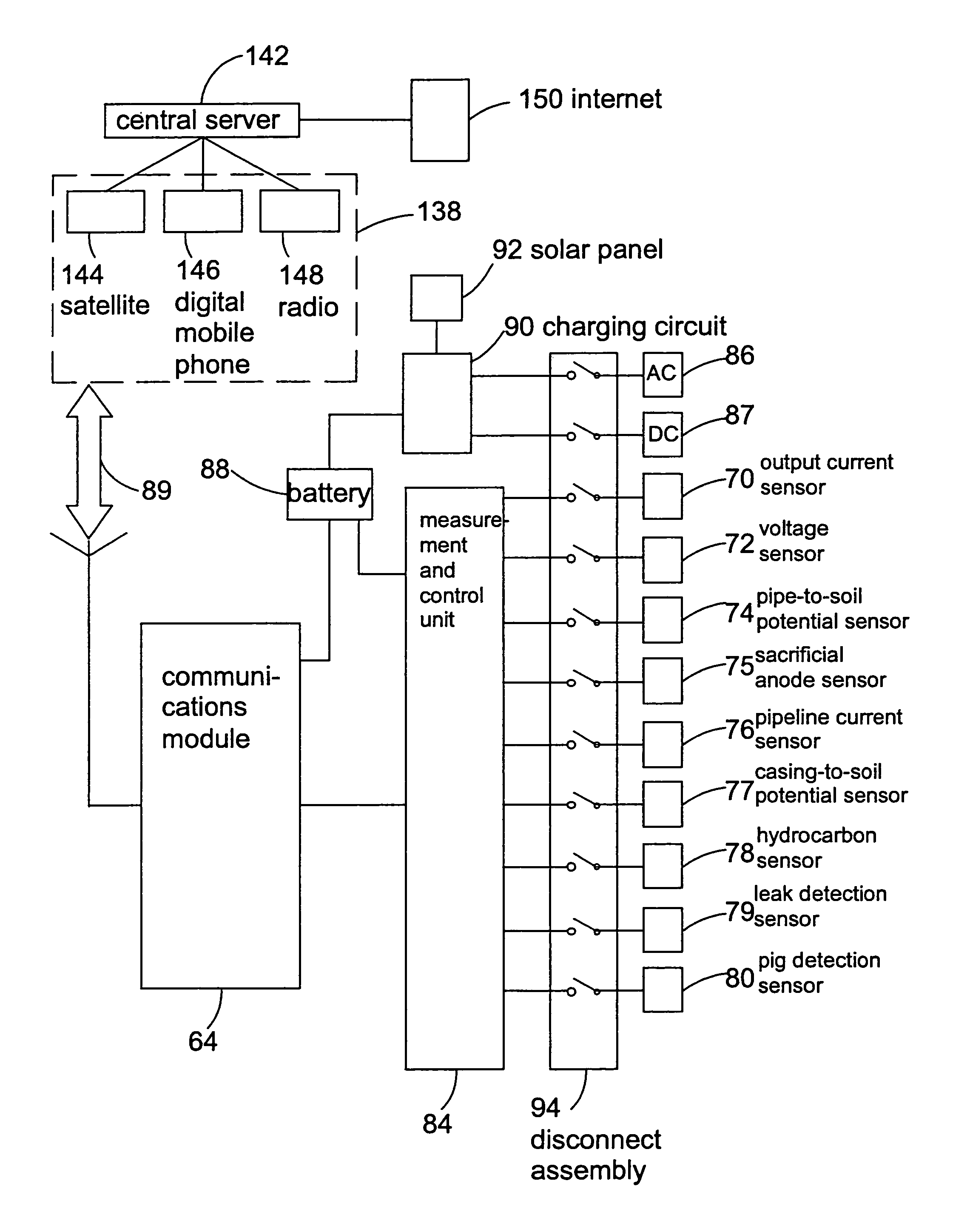
[0026]The remote monitoring unit is prone to damage by electrical surges. A switch is connected in the AC power and measuring circuits of the remote monitoring unit. The switch maintains the remote monitoring unit in the off position until a measurement is to be made. The switch has a disconnect position which separates the contacts between the remote monitoring unit and the AC power source and the measurement circuit a sufficient distance to prevent any electrical arc therebetween. The normally off position of the switch and the distance between the contacts on the switch prevent failure of the remote monitoring unit from electrical surges, thereby ensuring the successful operation and substantially increasing the lifetime of the remote monitoring units.

Problems solved by technology

The remote monitoring unit is prone to damage by electrical surges.

Method used


Image

  • Current interrupter assembly
  • Current interrupter assembly
  • Current interrupter assembly

Examples


Embodiment Construction

[0046]In the description which follows, like parts are marked throughout the specification and drawings with the same reference numerals, respectively. The drawing figures are not necessarily to scale. Certain features of the invention may be shown exaggerated in scale or in somewhat schematic form and some details of conventional elements may not be shown in the interest of clarity and conciseness.

[0047]The present invention relates to methods and apparatus for remotely monitoring cathodic protection. The method and apparatus is described for use in monitoring cathodic protection on a pipeline but it should be understood that the method and apparatus of the present invention is susceptible to embodiments of different forms and may be used for monitoring cathodic protection of any metal structure. There are shown in the drawings, and herein will be described in detail, specific embodiments of the present invention with the understanding that the present disclosure is to be considere...


PUM


Abstract

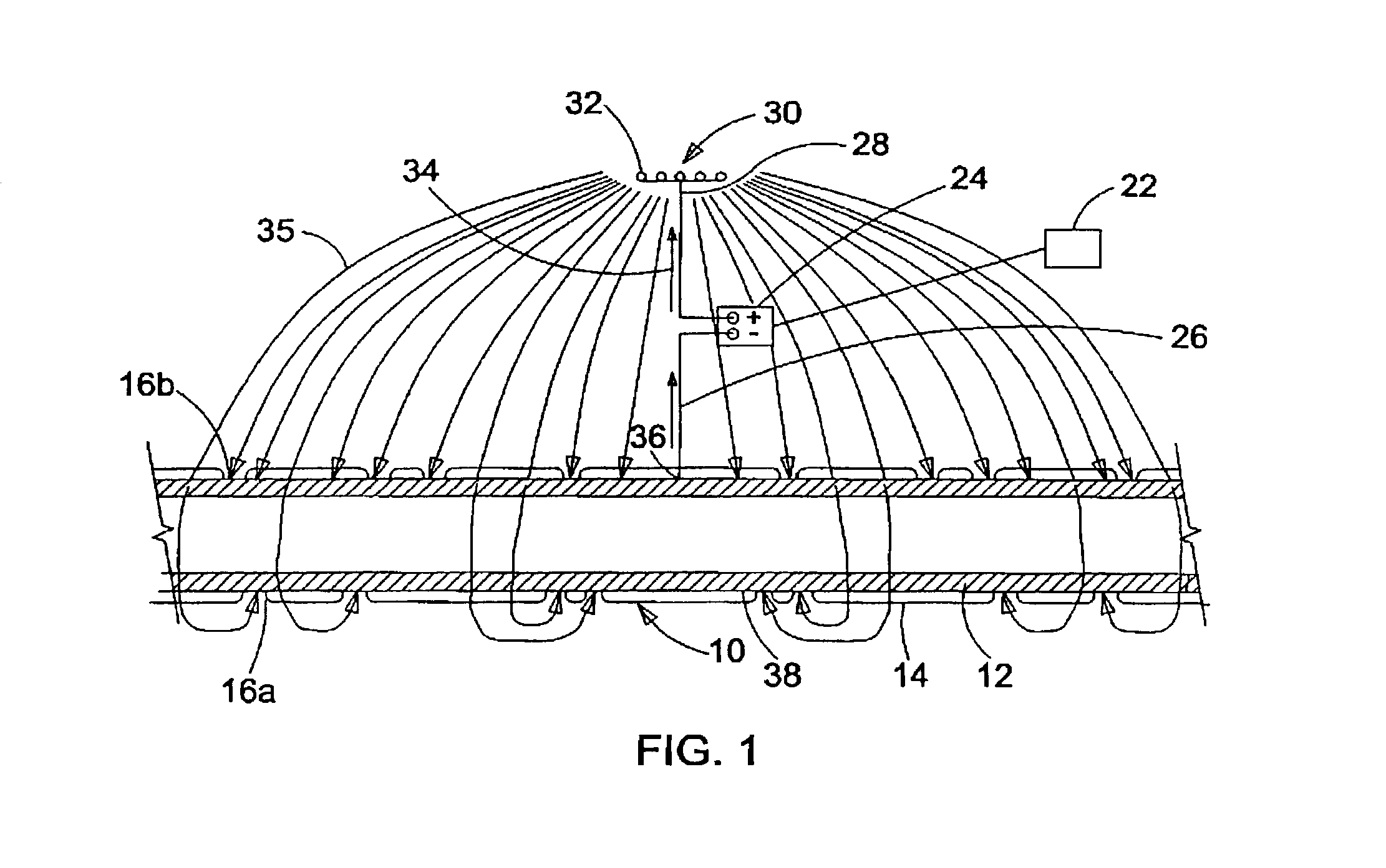
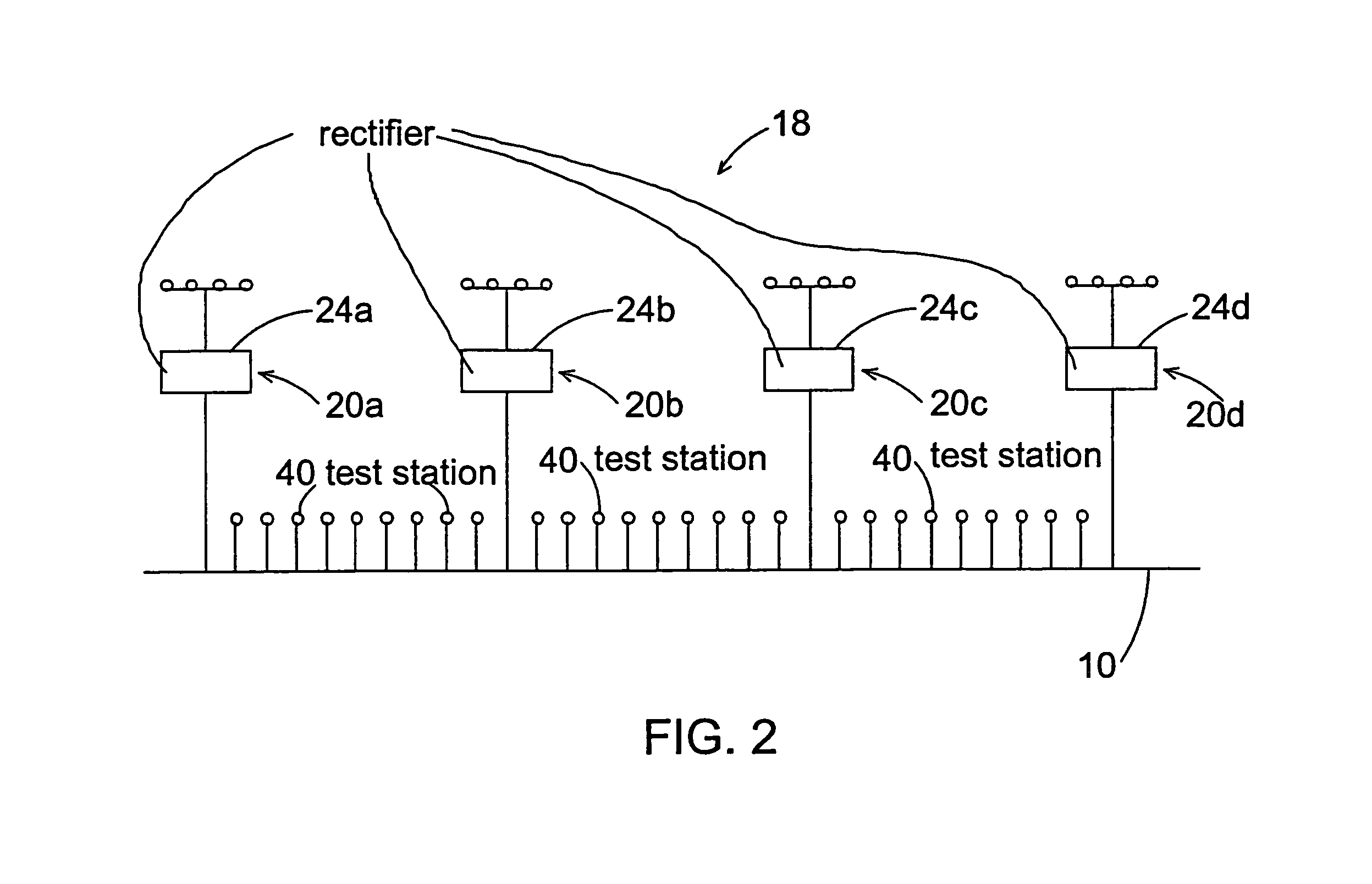
A method for determining the influence of one of a plurality of cathodic protection circuits along a pipeline includes switching one of a plurality of cathodic protection circuits off, while the remainder of the plurality of cathodic protection circuits are left on, with a portable pipe-to-soil potential measurement unit measuring the pipe-to-soil potential along the pipeline. From these measurements, a calibration curve is generated and an apparatus for monitoring the cathodic protection circuits is strategically positioned on the pipeline. The apparatus includes a remote monitoring unit having a pipe-to-soil potential measurement unit for measuring the potential between the ground bed and pipeline. The remote monitoring unit is off except while making measurements. The remote monitoring unit may optionally include a pipeline current measurement unit connected at a second connection point on the pipeline for measuring the current passing through the pipeline between the first and second connection points.

Description

CROSS-REFERENCE TO RELATED APPLICATIONS[0001]This application claims the benefit of U.S. Provisional Patent Application Ser. No. 60 / 329,022 filed Oct. 12, 2001, and U.S. Provisional Patent Application Ser. No. 60 / 348,845 filed Jan. 15, 2002, which are both hereby incorporated herein by reference in their entirety.STATEMENT REGARDING FEDERALLY SPONSORED RESEARCH OR DEVELOPMENT[0002]Not Applicable.FIELD OF THE INVENTION[0003]The present invention relates generally to a method and apparatus for remotely monitoring cathodic protection and more particularly to an apparatus for remotely monitoring cathodic protection of a pipeline. Still more particularly, the present invention relates to a remote monitoring assembly, resistant to power surges, that may be located at preferred remote locations along the pipeline and communicate cathodic protection operations to a central location.BACKGROUND OF THE INVENTION[0004]It is known that all metallic structures that come in contact with a medium h...

Claims


Application Information

Patent Timeline
IPC IPC(8): G06F15/00C23FG01R31/12G01R31/327G06F11/00
CPCG01R31/3275G01R31/12C23F2213/32
Inventor FOURIE, JULIUS W.OOSTHUYSEN, JOHAN
Owner AMERICAN INNOVATIONS MINNESOTA
Learn More