Compensated self-biasing current generator

a current generator and self-biased technology, applied in pulse generators, pulse techniques, instruments, etc., can solve the problems of ambient temperature and power supply variations of current generators, and achieve the effect of compensating current generators with temperature and power supply compensation

Inactive Publication Date: 2006-04-11
O2 MICRO INT LTD
View PDF17 Cites 25 Cited by
  • Summary
  • Abstract
  • Description
  • Claims
  • Application Information

AI Technical Summary

Problems solved by technology

However, such current generators are sensitive to ambient temperature and power supply variations.

Method used


Image

  • Compensated self-biasing current generator
  • Compensated self-biasing current generator
  • Compensated self-biasing current generator

Examples


Embodiment Construction

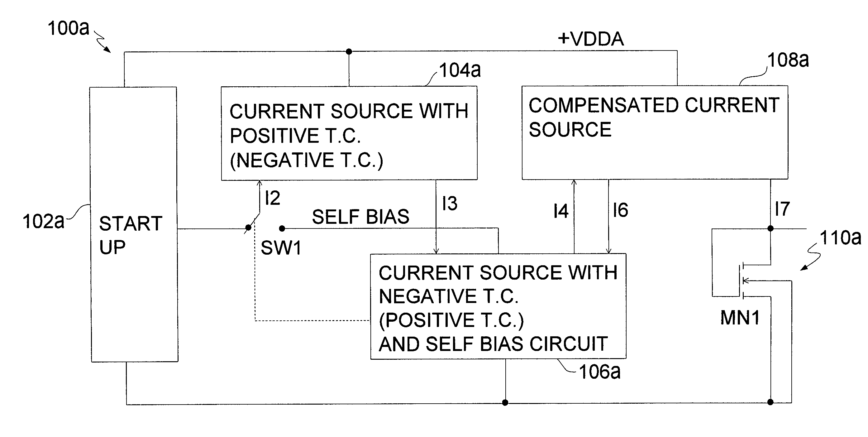
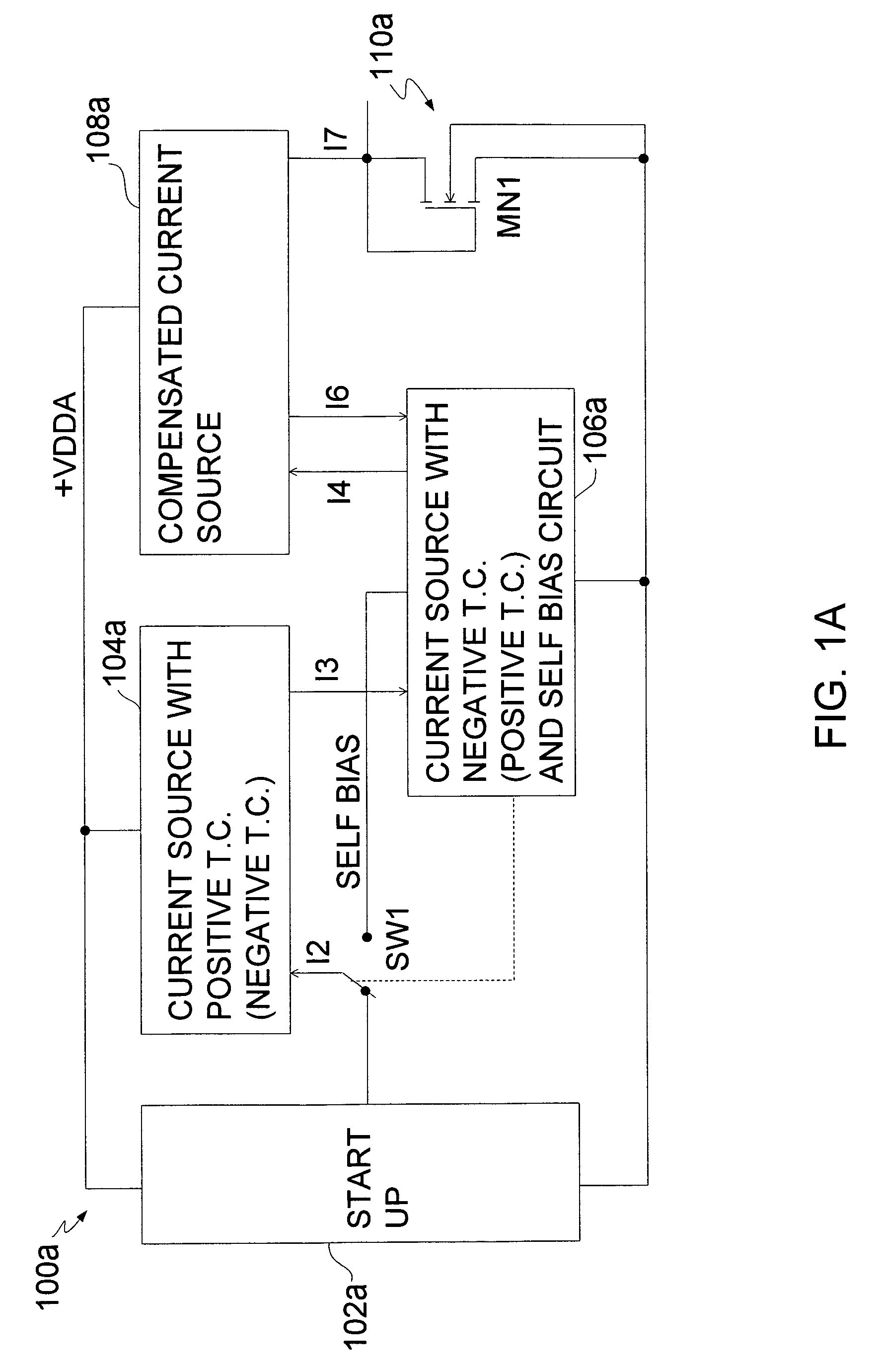
[0023]Turning to FIG. 1A, a compensated self-biasing current generator 100a consistent with the invention is illustrated. In general, the current generator 100a may include a start up circuit 102a, a first current source 104a with a first temperature coefficient, a second current source 106a with a second temperature coefficient, a compensated current source 108a, and an output circuit 110a.

[0024]The first temperature coefficient and the second temperature coefficient may have opposite signs. For instance, the first temperature coefficient may be a positive temperature coefficient such that its output current has a positive slope with respect to a positive change in ambient temperature (i.e., the output current increases when the temperature increases). If the first temperature coefficient is a positive temperature coefficient then the second temperature coefficient is a negative coefficient. A current source with a negative temperature coefficient has an output current having a ne...


PUM


Abstract

A compensated current generator includes a first current source and a second current source coupled in series. The first and second current sources have temperature coefficients with opposite signs to produce a temperature compensated current. The first current source may be a peaking current source biased by a bias signal to operate a peak of its transfer characteristic curve to enhance power supply rejection. An associated method is also provided.

Description

FIELD OF THE INVENTION[0001]This invention relates to current generators and in particular to temperature and power supply compensation of current generators.BACKGROUND OF THE INVENTION[0002]Current generators are utilized in a variety of circuits and applications. The generation of a constant current level is desirable given, among other things, that many analog circuits may be biased off such current generators. However, such current generators are sensitive to ambient temperature and power supply variations. For example, as ambient temperature varies over a wide range, e.g., from −40 degrees Celsius to +130 degrees Celsius, output current of the current generator may vary widely. In addition, as the power supply voltage level to such a current generator varies, e.g., from about 4.0 volts to 6.5 volts in one instance, the output current of the current generator may also vary widely. Traditional solutions, in one form or another, may use bipolar transistors in a way that a resultan...

Claims


Application Information

Patent Timeline
Patent Type & Authority Patents(United States)
IPC IPC(8): G05F1/10G05F1/00
CPCG05F3/16
Inventor GHEORGHIU, VIRGIL IOANYANG, THOMAS
Owner O2 MICRO INT LTD
Why Eureka
Try Eureka