
Rainwater collection apparatus and pumping system

Inactive Publication Date: 2006-04-11
TICKNOR MARTIN F
View PDF27 Cites 43 Cited by
  • Summary
  • Abstract
  • Description
  • Claims
  • Application Information

AI Technical Summary

Benefits of technology

[0018]It is a feature of the present invention to provide an apparatus with a removably attachable intake for acting as a filter and inhibit debris from ingress to a reservoir used for storing collected rainwater. The intake is attachable to the reservoir.
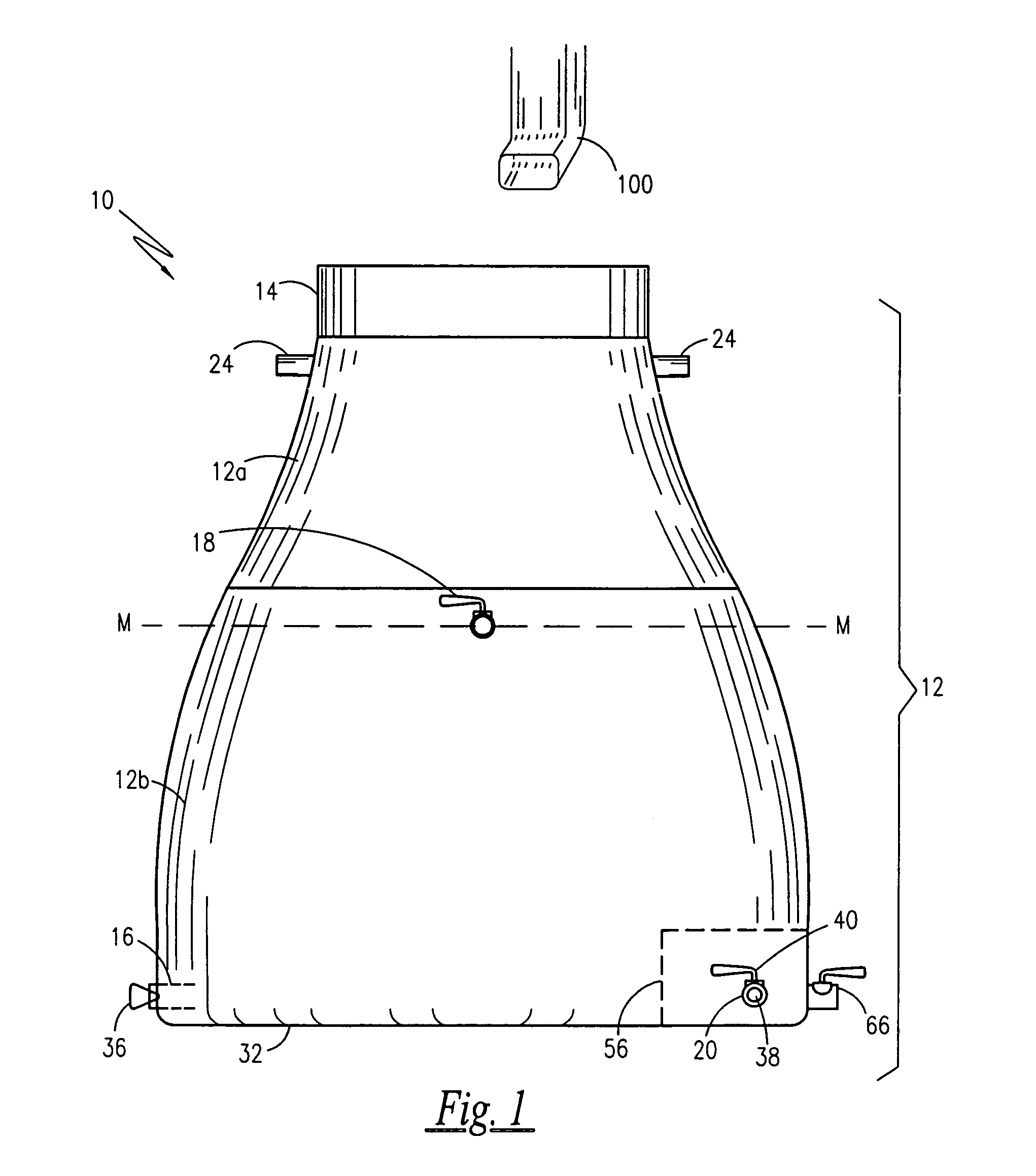
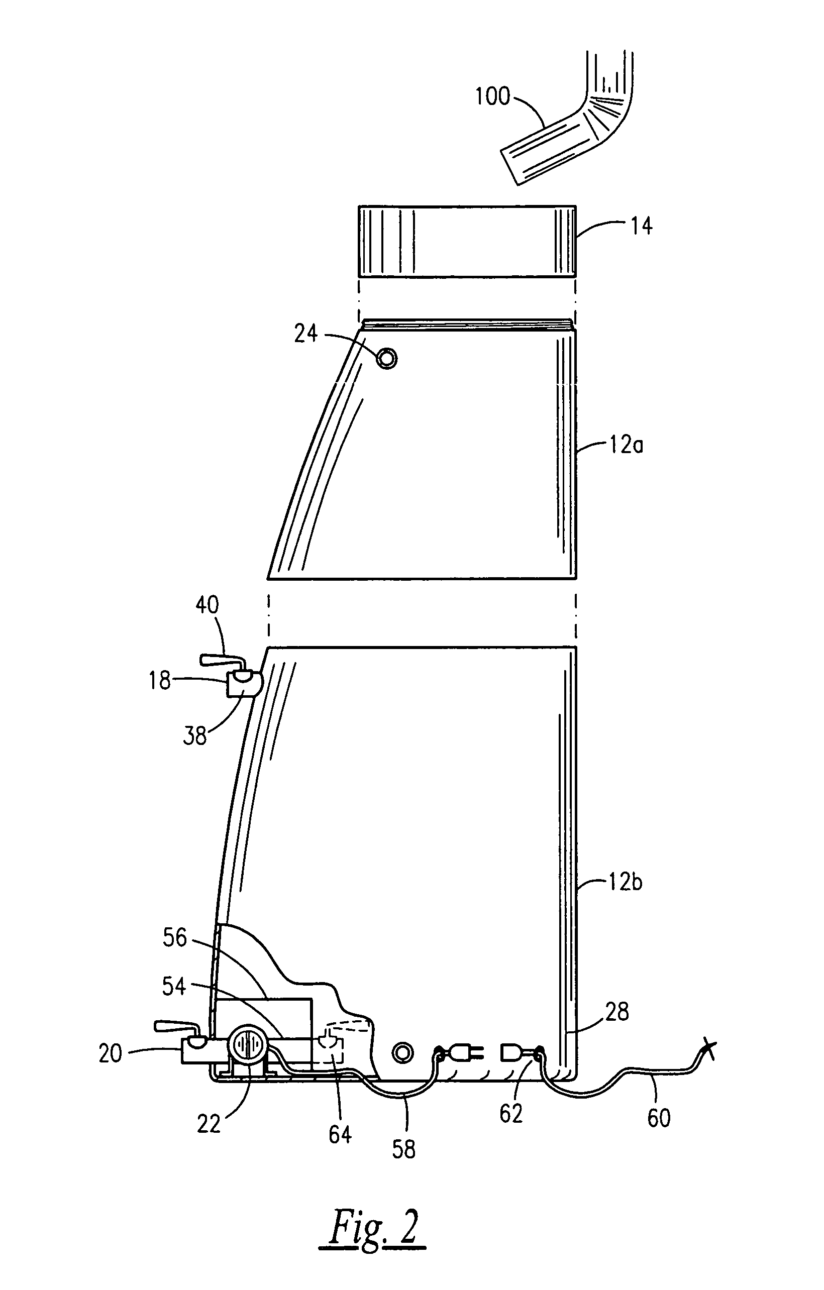
[0023]Briefly described according to one embodiment of the present invention, a rainwater collection apparatus operatively coupled with a pump is a reservoir positioned under a roof down-spout, which is typical of conventional cisterns. A lid is provided to keep foreign matter out. An overflow port or outlet is provided as well. At the bottom of the barrel, a drain fitting is provided to allow for winterization, cleaning or the like. To aid in the usage and distribution of the water, an internal submersible pump is provided. The output of the pump is connected to a conventional garden hose allowing the rain water from the barrel to be used for washing of motor vehicles, watering of lawns and flowers, rinsing of driveways and the like. The pump is controlled by an ON-OFF switch located on the side of the barrel. The use of the apparatus provides an easy means of using rain water from a cistern, thus promoting water conservation in a manner which is easy, cost-effective and efficient.

Problems solved by technology

However, the typical cistern that collects roof rain water usually only has a removable lid which allows a person to dunk a pail inside to fill it.
As such, it is not easy or even handy for use for everyday chores, thus such rain water is left unused, while the municipal or well system is used for water.

Method used


Image

  • Rainwater collection apparatus and pumping system
  • Rainwater collection apparatus and pumping system
  • Rainwater collection apparatus and pumping system

Examples


Embodiment Construction

[0032]The best mode for carrying out the invention is presented in terms of its preferred embodiment, herein depicted within the FIGS. 1–7.

[0033]1. Detailed Description of the Figures

[0034]Referring now to FIG. 1 through FIG. 7, a rainwater collection apparatus 10 is shown in accordance with a preferred embodiment of the present invention. The apparatus 10 comprises a reservoir 12 and a removable intake 14. The reservoir 12 includes a drainage port 16 and a first outlet 18. The reservoir 12 may also include a second outlet 20 for exporting water or potentially working in combination with drainage port 16. The apparatus 10 may further comprises a pump 22 either submersible within the reservoir 12 or independent of the reservoir 12, operatively coupled with the reservoir 12 to pump water from the reservoir 12 through the second outlet 20. The apparatus 10 may also include at least one (or more) overflow ports 24 provided to permit overflow rainwater to egress from the reservoir 12 in ...


PUM

PropertyMeasurementUnit
Distributionaaaaaaaaaa

Abstract

A rainwater collection apparatus stores rainwater until required, and includes at least one outlet for exporting rainwater. The outlet or outlets include ball-valve assemblies and levers for opening and closing the outlets, and couplers for attachment to a garden hose, thereby providing optimal control of the export of water. An overflow port or outlet is provided as well. A drainage port at an inferior end is provided to remove sediment. To aid in the usage and distribution of the water, an internal submersible pump may be provided. The output of the pump is connected to a conventional garden hose allowing the rain water from the barrel to be used for washing of motor vehicles, watering of lawns and flowers, rinsing of driveways and the like. The pump is controlled by an ON-OFF switch located on the side of the barrel.

Description

RELATED APPLICATIONS[0001]The present invention contains subject matter that was first described in Disclosure Document Registration 539,109 filed on Sep. 24, 2003 under 35 U.S.C. §122 and 37 C.F.R. §1.14. As such, it is respectfully requested that said Disclosure Document remain a permanent part of the file history of the present application and be relied upon during the pending prosecution, and for any other matters that may arise.[0002]There are no previously filed, nor currently any co-pending applications, anywhere in the world.BACKGROUND OF THE INVENTION[0003]1. Field of the Invention[0004]The present invention relates generally to a rainwater collection apparatus and, more particularly, to a rainwater collection apparatus with plural outlets and a submersible pump for export or evacuation of water, and a drainage port for exporting sediment.[0005]2. Description of the Related Art[0006]Many homes and communities rely on cisterns for storing collected water. A cistern is basica...

Claims


Application Information

Patent Timeline
IPC IPC(8): B01D29/00B01D29/92
CPCE03B3/03Y02A20/108Y02A20/00
Inventor TICKNOR, MARTIN F.
Owner TICKNOR MARTIN F
Learn More