
Knee joint prosthesis

Inactive Publication Date: 2006-04-11
BIOMET MFG CORP
View PDF19 Cites 136 Cited by
  • Summary
  • Abstract
  • Description
  • Claims
  • Application Information

AI Technical Summary

Benefits of technology

[0007]One particular advantage of the present invention is to provide a tibial component of a knee joint prosthesis having a common tibial tray and a plurality of tibial stems with various offsets for selectively engaging the tibial tray.
[0008]Another advantage of the present invention is to provide a tibial component of a knee joint prosthesis having a offset modular stem that securely engages a tibial tray.
[0009]Another advantage of the present invention is to provide a modular component of a knee joint prosthesis that permits different degrees of stem offset with minimal inventory.
[0010]Another advantage of the present invention is the provision of a tibial component of a knee joint prosthesis having a stem which is offset immediately below a tibial tray.
[0011]Another advantage of the present invention is the provision of a modular tibial component of a knee joint prosthesis having a stem that easily and securely engages a tray.
[0012]Another advantage of the present invention is the provision of a modular tibial component of a knee joint prosthesis which provides an offset in any direction within the transverse plane.

Problems solved by technology

Although a central location of the stem allows for particular implant to be used for either the right or left knee, such a stem position is associated with drawbacks.
The primary drawback is that the centrally located stem was substantially offset from the center of the tibial canal itself when the base of the implant was aligned with the resected tibial surface.

Method used


Image

  • Knee joint prosthesis
  • Knee joint prosthesis
  • Knee joint prosthesis

Examples


Embodiment Construction

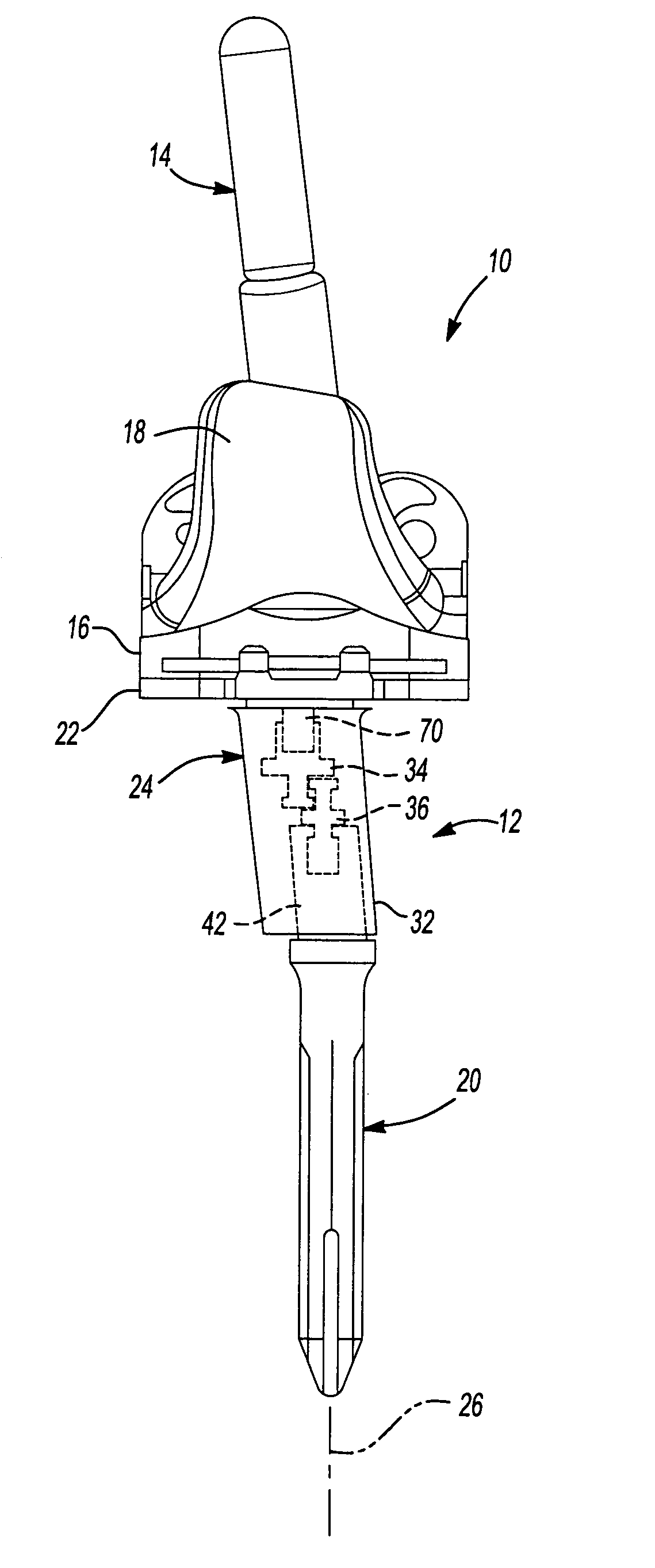
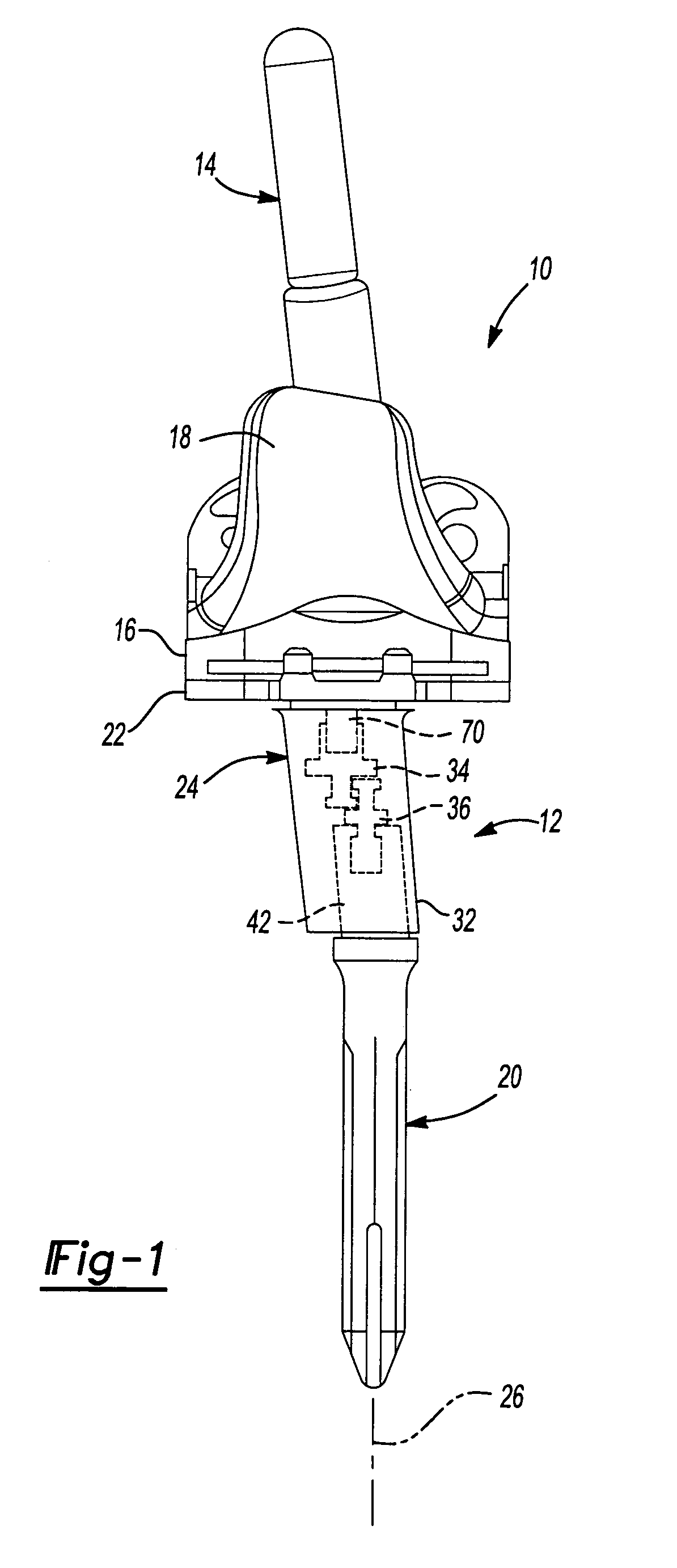
[0037]With initial reference to FIG. 1, a knee joint prosthesis constructed in accordance with the teachings of a preferred embodiment of the present invention is illustrated and generally identified at reference number 10. The knee joint prosthesis 10 is generally shown to include a tibial component 12 and a femoral component 14. The tibial component 12 supports a bearing 16 which engages an articulation surface 18 of the femoral component 14. Insofar as the present invention is concerned, it will be understood that the femoral component 14 and the bearing 16 shown in FIG. 1 are conventional in construction.

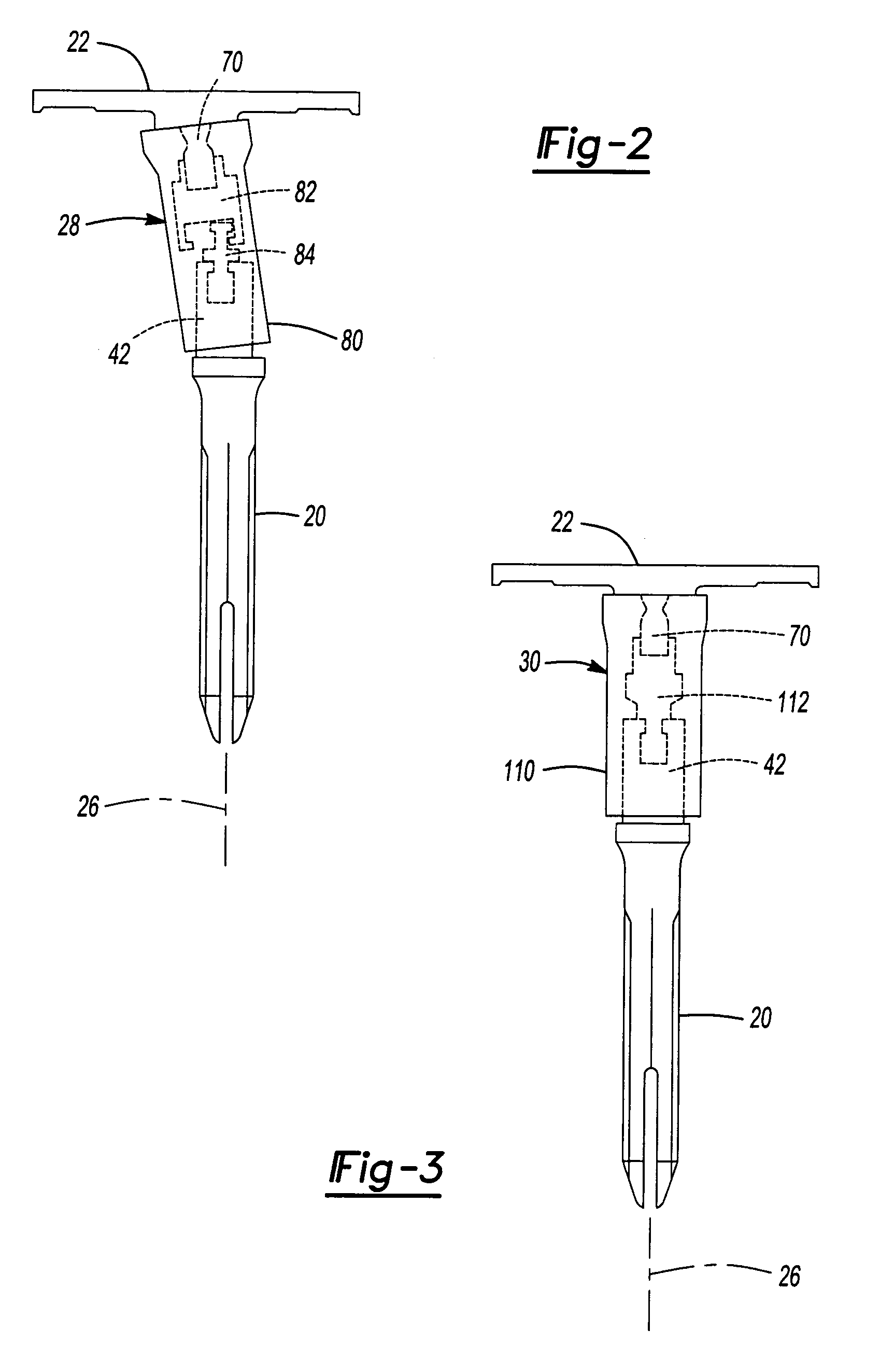
[0038]The tibial component 12 illustrated in FIG. 1 will be understood to be modular in construction and generally include a stem 20, a tray 22, and a first adapter assembly 24. In a manner which will be discussed more fully below, the adapter assembly 24 connects the tray 22 and the stem 20 so as to provide an offset to the stem 20 in the transverse plane. Explaining further, w...


PUM


Abstract

A modular tibial component for a knee joint prosthesis. The modular tibial component includes a tray, a stem and an adapter assembly. The tray includes a support surface and downwardly extending extension having a generally circular shape. The stem includes a main body portion and an upwardly extending extension. The adapter assembly connects the tray and the stem. The adapter assembly includes a first generally cylindrical cavity receiving the downwardly extending extension of the tray and a second generally cylindrical cavity receiving the upwardly extension of the stem.

Description

CROSS-REFERENCE TO RELATED APPLICATIONS[0001]This is a continuation-in-part application of U.S. Ser. No. 09 / 792,172, filed Feb. 23, 2001, now abandoned.FIELD OF THE INVENTION[0002]The present invention relates generally to a joint prosthesis and more particularly to a knee joint prosthesis having a modular tibial component with an offset tibial stem.BACKGROUND OF THE INVENTION[0003]A knee joint prosthesis typically comprises a femoral component and a tibial component. The femoral component and tibial component are designed to be surgically attached to the distal end of the femur and the proximal end of the tibia respectively. The femoral component is further designed to cooperate with the tibial component in simulating the articulating motion of an anatomical knee joint. Knee joint prostheses, in combination with ligaments and muscles, attempt to duplicate natural knee motion as well as absorb and control forces generated during the range of flexion.[0004]While known knee joint pros...

Claims


Application Information

Patent Timeline
IPC IPC(8): A61F2/38A61F2/00A61F2/02A61F2/30A61F2/46
CPCA61F2/30721A61F2/38A61F2250/0006A61F2002/30133A61F2002/30143A61F2002/30154A61F2002/30329A61F2002/30336A61F2002/30342A61F2002/30354A61F2002/30357A61F2002/30405A61F2002/30433A61F2002/30476A61F2002/30538A61F2002/30574A61F2002/30594A61F2002/30604A61F2002/30616A61F2002/30774A61F2002/3079A61F2002/30794A61F2002/30797A61F2002/30878A61F2002/4638A61F2220/0025A61F2220/0033A61F2220/0041A61F2230/0015A61F2230/0017A61F2230/0021A61F2002/30339
Inventor METZGER, ROBERT G.HOEPPNER, JACY C.
Owner BIOMET MFG CORP
Learn More