
Light guide member and illuminating device

a technology of light guide and illuminating device, which is applied in waveguides, lighting and heating apparatus, instruments, etc., can solve the problem of extremely reduced display visibility, and achieve the effect of efficient illumination

Inactive Publication Date: 2006-04-11
ALPS ALPINE CO LTD
View PDF6 Cites 130 Cited by
  • Summary
  • Abstract
  • Description
  • Claims
  • Application Information

AI Technical Summary

Benefits of technology

[0009]The present invention is made in consideration of the above situation, and an object of the present invention is to provide a light guide member and an illuminating device which are able to efficiently and uniformly irradiate the illumination light to only an area requiring the illumination.
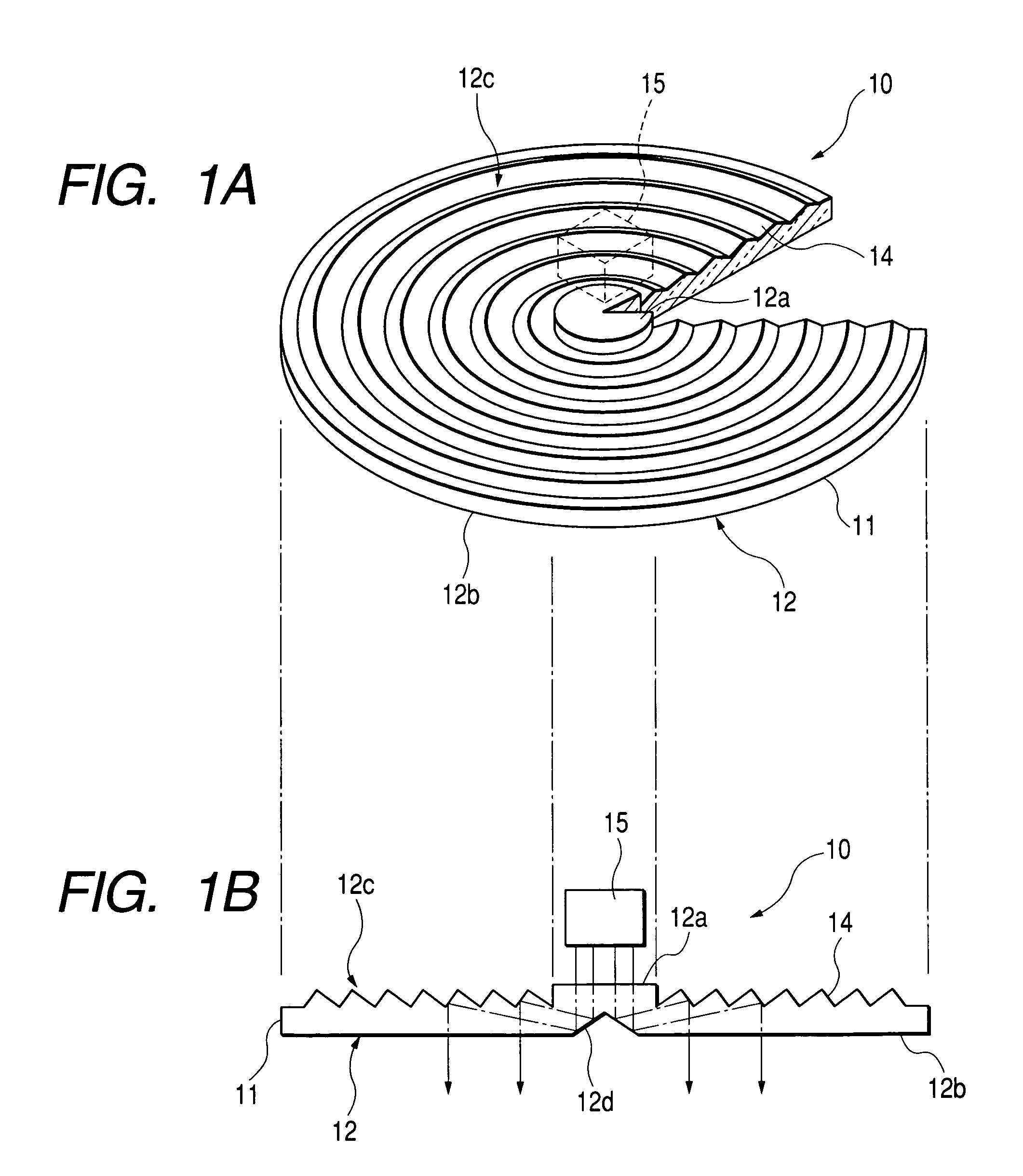
[0011]In accordance with such a light guide member, the illumination light emitted from the emitting face is illuminated to only the same range as the shape of the reflection face. If the shape of the reflection face is set to the range actually requiring the illumination, only the range actually requiring the illumination is illuminated and no illumination light is irradiated to its circumference. Thus, the difference in contrast between the circumferential portion and the illumination range is raised and visibility of the illumination range is further raised.
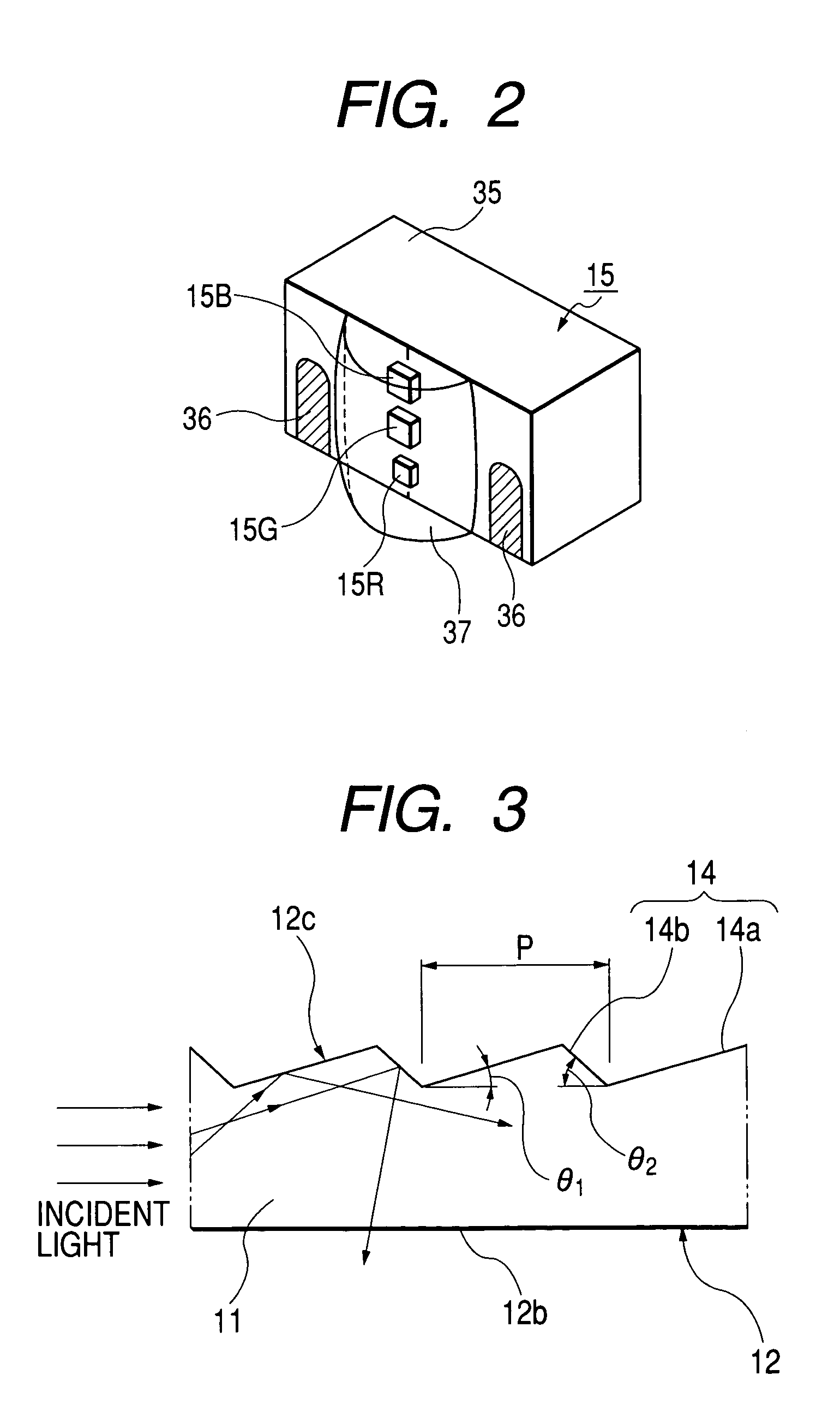
[0012]The reflection stripes may be grooves constructed by two faces having inclination angles different from each other with respect to the emitting face, or are a reflection prism for reflecting the light on the surface. The reflection face constructed by such reflection stripes reflects the light without irregularities. A diffusing portion for diffusing the light toward the reflection face may be further arranged on the way of an optical path from the incident face to the reflection face. The diffusing portion is greatly useful to widen the light of the light source toward the reflection face without irregularities. The diffusing portion may be constructed by a reflection prism for reflecting the light on the surface.
[0015]In accordance with such a light guide member, the uniform light having no irregularities can be irradiated so as to be widened toward the outside of the endless light guide body. If this light guide member is arranged at the center of an illuminated object, the illuminated object can be brightly illuminated in a ring shape. If the above light guide member and the light source are arranged in the illuminating device, the illuminating device which is able to efficiently clearly illuminate the illuminated object of an arbitrary shape can be provided.

Problems solved by technology

Therefore, in an environment in which no sufficient circumferential light is obtained at the time of using in a dark place, etc., visibility of the display is extremely reduced.

Method used


Image

  • Light guide member and illuminating device
  • Light guide member and illuminating device
  • Light guide member and illuminating device

Examples


Embodiment Construction

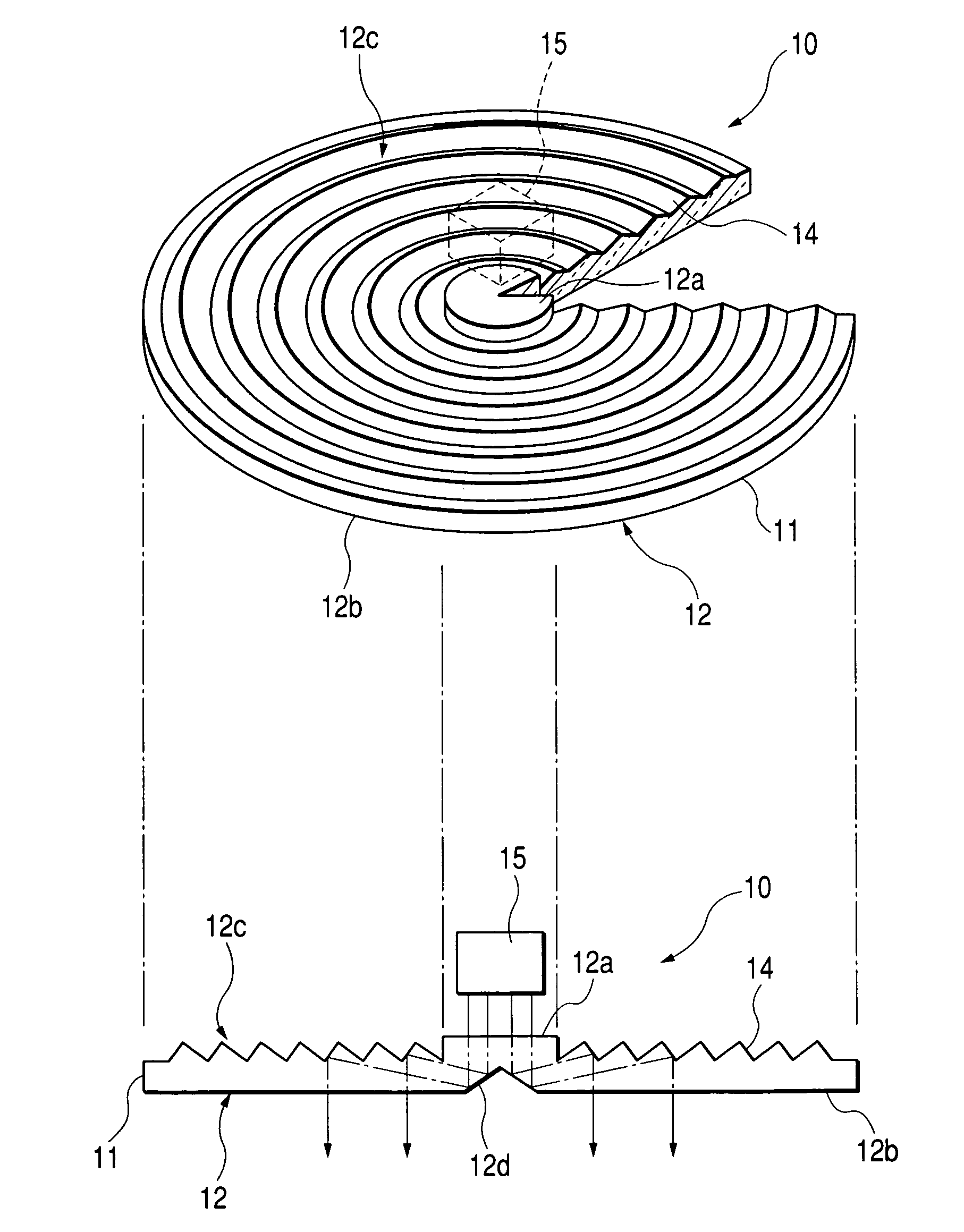
[0023]The embodiment modes of the present invention will next be explained with reference to the drawings. FIG. 1A is a partially broken perspective view of a front light (illuminating device) in one embodiment mode of an illuminating device of the present invention. FIG. 1B is a cross-sectional view of the front light shown in FIG. 1A. The front light (illuminating device) 10 is constructed by arranging a flat-shaped light guide member 12 made of a transparent resin material, and a light source unit (light source) 15 arranged on the central line of this light guide member 12.

[0024]The light guide member 12 has a light guide portion 11 formed in a transparent disc shape and propagating light in its interior, an incident face 12a formed at the-center of the light guide portion 11 and introducing light into the light guide portion 11, an emitting face 12b for emitting the light introduced into the light guide portion 11, a reflection face 12c constructed by many reflection stripes 14 ...


PUM


Abstract

The invention provides a light guide member and an illuminating device which are able to efficiently uniformly irradiate illumination light to only an area requiring illumination. Therefore, a reflection face is constructed by reflection stripes such as many grooves, etc. widened in a concentric circle shape. Light from a light source unit is widened toward this entire reflection face without irregularities by a diffusing portion such as a reflection prism, etc. Thus, only the range actually requiring the illumination can be illuminated without irregularities, and visibility of the illumination range using a front light is raised.

Description

BACKGROUND OF THE INVENTION[0001]1. Field of the Invention[0002]The present invention relates to a light guide member for propagating light from an incident face toward an emitting face and an illuminating device having this light guide member.[0003]2. Description of the Related Art[0004]In a reflection type liquid crystal display device for performing a displaying operation with circumferential light as a light source, its brightness is influenced by the light amount of the circumferential light. Therefore, in an environment in which no sufficient circumferential light is obtained at the time of using in a dark place, etc., visibility of the display is extremely reduced. Therefore, a liquid crystal display device having a front light (face light emitting illuminating device) arranged on the front face side of the liquid crystal display unit (liquid crystal display element) of the reflection type, and used as an auxiliary light source is proposed. This liquid crystal display device ...

Claims


Application Information

Patent Timeline
IPC IPC(8): F21V9/00G02B6/00F21V5/04F21V8/00F21Y101/02G02B27/09
CPCG02B6/0018G02B6/0038B60K35/00Y10S385/901B60K2350/203B60K2360/33
Inventor YAMASHITA, TATSUMAROHAYASHI
Owner ALPS ALPINE CO LTD
Learn More