Eureka AIR delivers breakthrough ideas for toughest innovation challenges, trusted by R&D personnel around the world.

Rear projection television with screen panel for receiving projection light

Inactive Publication Date: 2006-04-11
SEIKO EPSON CORP
View PDF4 Cites 3 Cited by
  • Summary
  • Abstract
  • Description
  • Claims
  • Application Information

AI Technical Summary

Benefits of technology

[0009]According to this rear projection television, when the working door is opened, the detector section detects opening of the working door and outputs the detection signal, and in response to the detection signal, the control section causes the illumination lamp to light to illuminate the inside of the body. This makes it possible to view the light source lamp clearly through the opening opened by the working door. Further, it is no longer necessary to illuminate the inside of the apparatus body e.g. by a flashlight, and therefore, a user can use both hands to remove and mount light source lamps and carry out repair work within the body, which facilitates replacement of a burned-out light source lamp and repair work within the body.
[0010]It is preferable that the working door is arranged for opening and closing a replacement work opening formed in the body for replacement of the light source lamp, and the illumination lamp illuminates an area around the light source lamp. With this arrangement, when the working door is opened, the replacement work opening becomes open, and the illumination lamp illuminates the area around the light source lamp. Therefore, the area around the light source lamp can be clearly viewed through the opening, which makes it possible to replace a burned-out light source lamp more easily.
[0011]Preferably, the control section stops supply of electric power to the light source lamp when the detection signal is outputted by the detector section. With this arrangement of the preferred embodiment, even when the replacement work is performed without turning off a switch for switching between supply and cutoff of the supply of electric power to the light source lamp, since the supply of electric power to the light source lamp has already been cut off, the user can perform the replacement work without receiving an electric shock even if the user's hand touches e.g. a socket for the light source lamp.
[0012]Preferably, the control section causes the illumination lamp to flash when the detection signal is outputted by the detector section in a state where electric power is supplied to the light source lamp. With this arrangement of the preferred embodiment, when the replacement work is performed without turning off the switch for switching between supply and cutoff of the supply of electric power to the light source lamp, the flashing of the illumination lamp informs the user of the abnormal operation, so that the user can turn off the switch. Further, even when the rear projection television is not provided with the switch, the user can perform the work cautiously. Thus, it is possible to safely carry out replacement work on the light source lamp.
[0014]Preferably, the illumination lamp is formed by a solid light source. With this arrangement, since the solid light source is generally excellent in durability and efficiency, the area around the light source lamp can be efficiently illuminated over a long time period.
[0015]Preferably, the rear projection television comprises a main power supply for supplying electric power to the light source lamp, and an auxiliary power supply for supplying electric power to the illumination lamp, and the auxiliary light source is capable of storing electric charge. With this arrangement, even when an AC plug of the television is not connected to a commercial AC power outlet, it is possible to illuminate the inside of the body.

Problems solved by technology

However, in general, a light source lamp of a projector can burn out after approximately 10,000 hours of use.
Therefore, the rear projection television of the above mentioned kind presents a problem that a user has to do troublesome work of moving the rear projection television and detaching the rear panel for replacement of the light source lamp.
However, from the study of the above described liquid crystal projection television receiver, the inventor found out the following problem: In general, the inside of the cabinet of a liquid crystal projection television receiver of this kind is dark.
This makes it difficult for the user to view the light source lamp unit through the window of the cabinet, and hence he has to grope for the light source lamp unit to replace the same.
Therefore, this liquid crystal projection television receiver suffers from the problem of difficulty of the very work of replacing the light source lamp unit.
In this method, however, the user can use only one hand to mount or remove the light source lamp unit, and hence it still remains difficult to carry out the very work of replacing the light source lamp unit.

Method used


Image

  • Rear projection television with screen panel for receiving projection light
  • Rear projection television with screen panel for receiving projection light
  • Rear projection television with screen panel for receiving projection light

Examples


Embodiment Construction

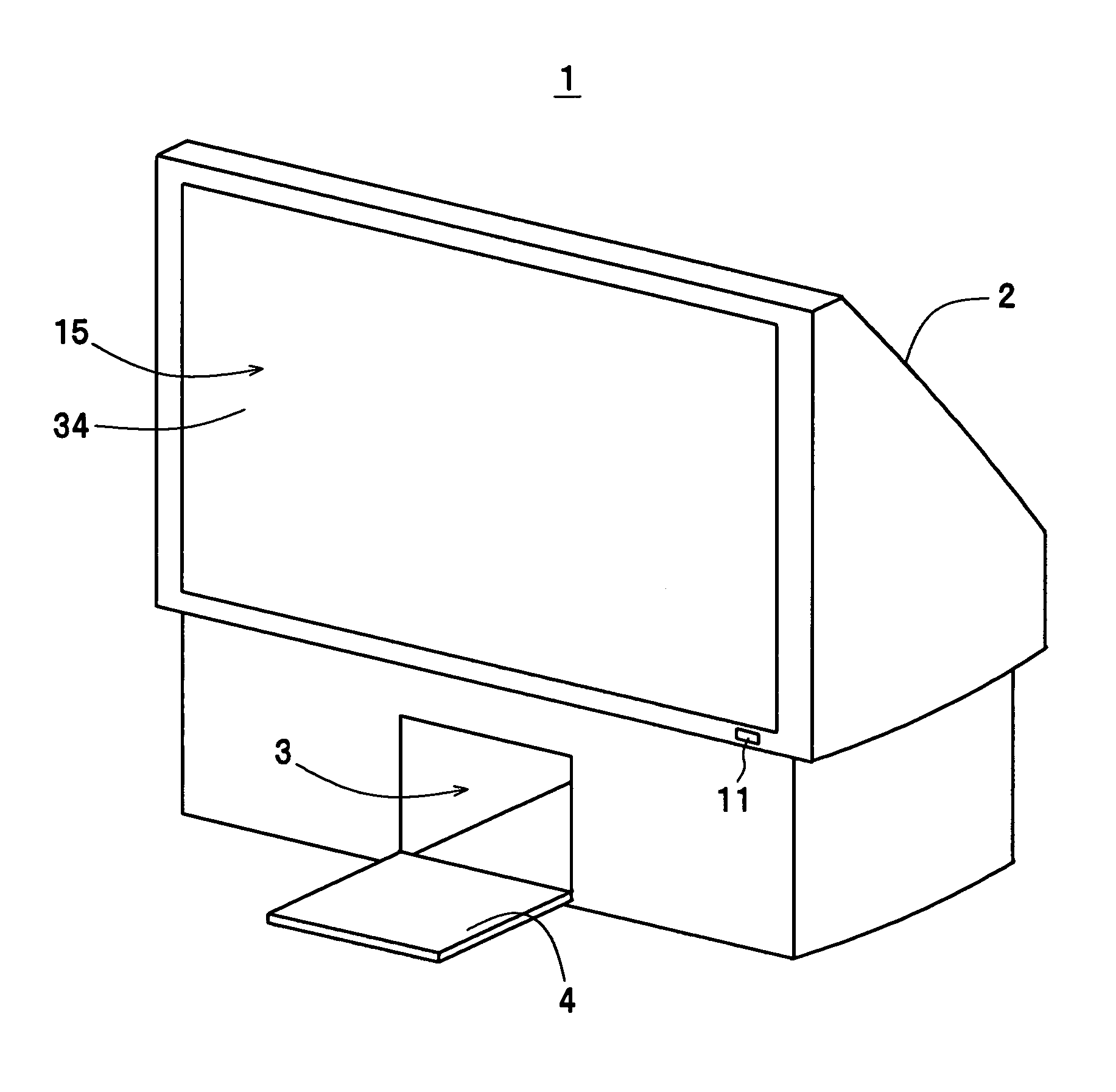
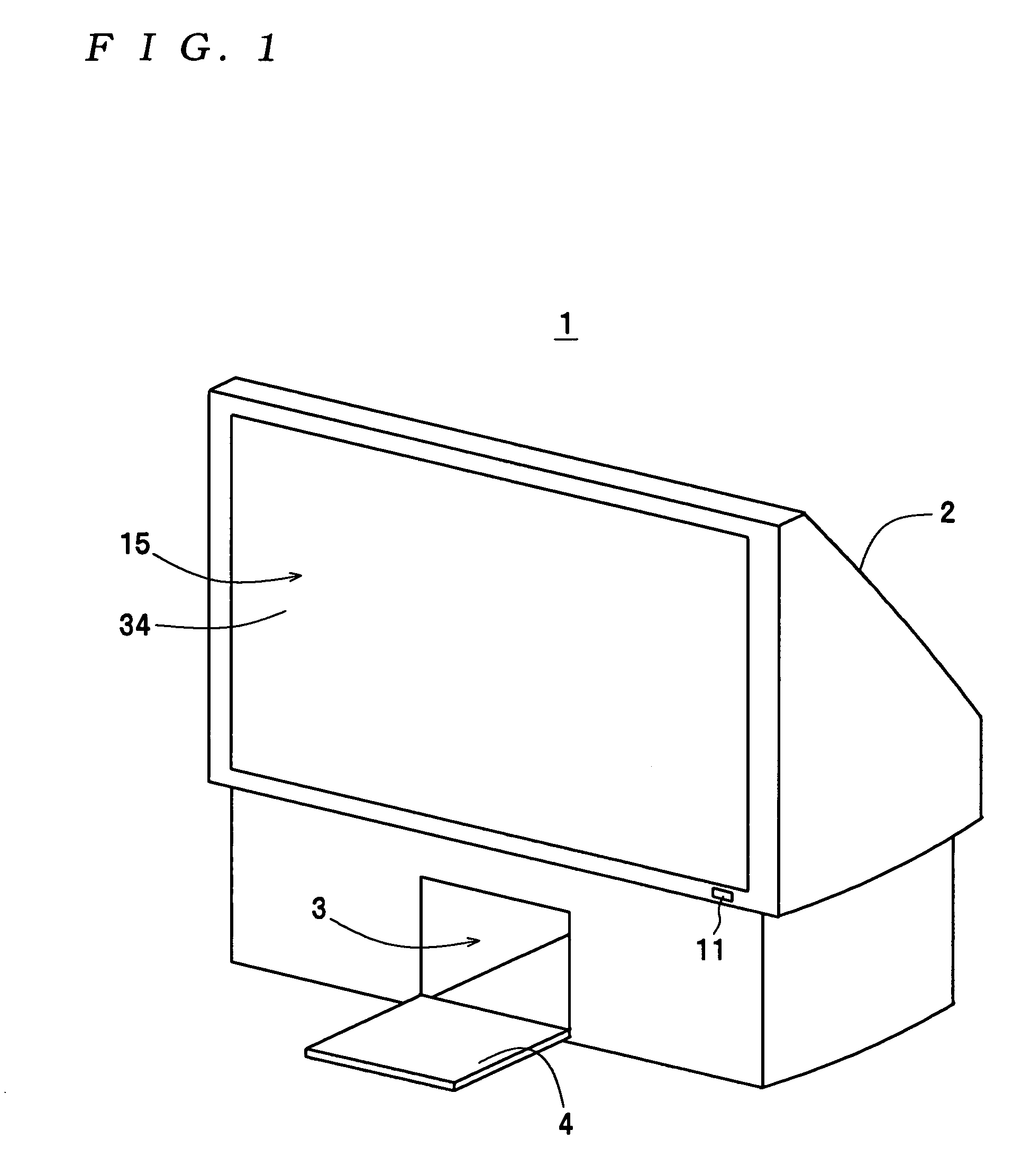
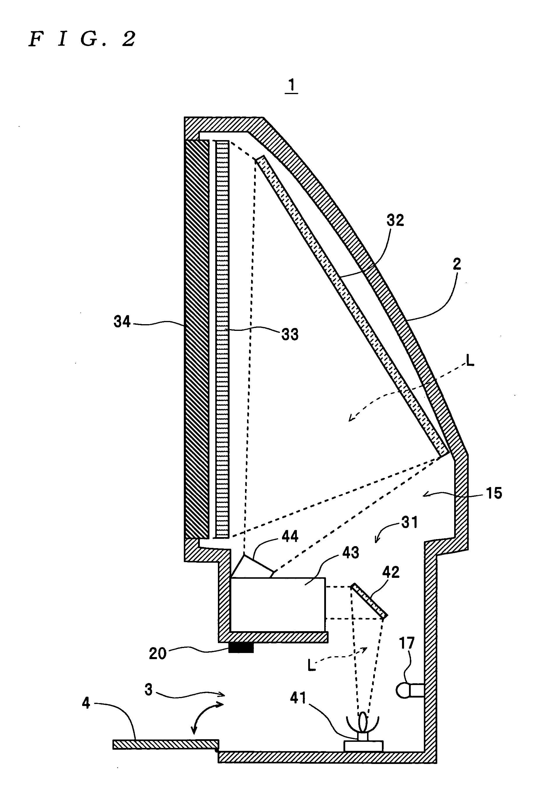
[0021]The invention will now be described with reference to the accompanying drawings showing the best mode of the present invention. First, a description will be given of the arrangement of a rear projection television (hereinafter also simply referred to as “the television”) 1. As shown in FIGS. 1 and 2, the television 1 is capable of displaying an image on a screen panel 34 that is disposed at the front of a cabinet (body) 2 and forms a part of a display 15 described in detail hereinafter, by projecting projection light L from behind the screen panel 34. More specifically, as shown in FIG. 3, the television 1 is comprised of a main switch 11, a main power supply 12, an auxiliary power supply 13, a switch 14, the display 15, a lamp-driving circuit 16, an illumination section 17 for replacement work, a control section 18 and an opening-detecting sensor 20. These component parts and elements are accommodated in the cabinet 2 or mounted on the outside of the cabinet 2. Further, as sh...


PUM


Abstract

There is provided a rear projection television having a construction which facilitates replacement of a light source lamp and repair work within the body. The rear projection television includes a screen panel disposed at the front of a cabinet thereof, for receiving projection light projected from behind for image display, to thereby display an image thereon, a light source lamp removably disposed within the cabinet, for projecting the projection light, and a working door provided in the front face of the cabinet. An opening-detecting sensor detects opening of the working door and outputs an opening-detecting signal. An illumination section for replacement work disposed within the cabinet illuminates the inside of the body. The control section causes the illumination section to light when the opening-detecting signal is outputted by the opening-detecting sensor.

Description

BACKGROUND OF THE INVENTION[0001]1. Field of the Invention[0002]The present invention relates to a rear projection television in which projection light is projected from behind a screen panel to thereby display an image on the screen panel.[0003]2. Description of the Related Art[0004]With proliferation of digital broadcasting and widespread use of digital AV (audio-visual) apparatuses in recent years, there has been a growing demand for televisions capable of displaying images of high quality on respective large screens. As a television of this kind, a rear projection television has been conventionally proposed which displays images by the rear projection method. In the rear projection television, a projector disposed within a cabinet projects projection light onto a light transmission screen panel disposed at the front of the cabinet, from behind, to thereby display an image on the screen panel. In this case, the projector includes a light source lamp, such as a high-pressure mercu...

Claims


Application Information

Patent Timeline
IPC IPC(8): G03B21/14G03B21/20G03B21/22G03B21/26G03B21/00G03B21/10H04N5/74
CPCG03B21/10H04N9/3141H04N5/7408H04N5/74
Inventor KIMURA, KEISHITSUKINOKIZAWA, CHIHIRO
Owner SEIKO EPSON CORP
Why Eureka
Eureka Blog
Learn More