
Ball bearing actuation mechanism

a ball bearing and actuation mechanism technology, applied in the field of vending machines, can solve problems such as the annoyance of most players

Inactive Publication Date: 2006-04-11
CHANG KIL JAE
View PDF13 Cites 23 Cited by
  • Summary
  • Abstract
  • Description
  • Claims
  • Application Information

AI Technical Summary

Benefits of technology

[0006]The present invention provides a ball bearing actuation mechanism for a vending machine which is designed to satisfy the aforementioned need. The actuation mechanism is designed to allow a quantity of ball bearings to be deposited into the ...

Problems solved by technology

This requirement is a problem for the players in that it takes concentration and time and thus constitutes a considerable annoyance for most players.

Method used


Image

  • Ball bearing actuation mechanism
  • Ball bearing actuation mechanism
  • Ball bearing actuation mechanism

Examples


Embodiment Construction

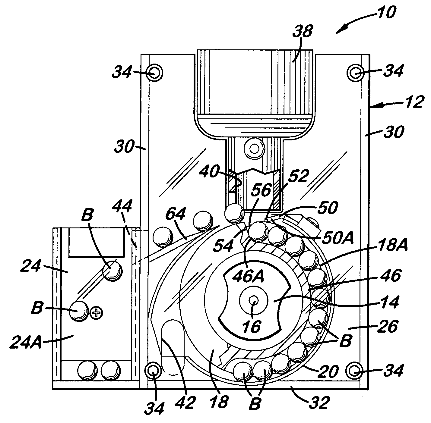
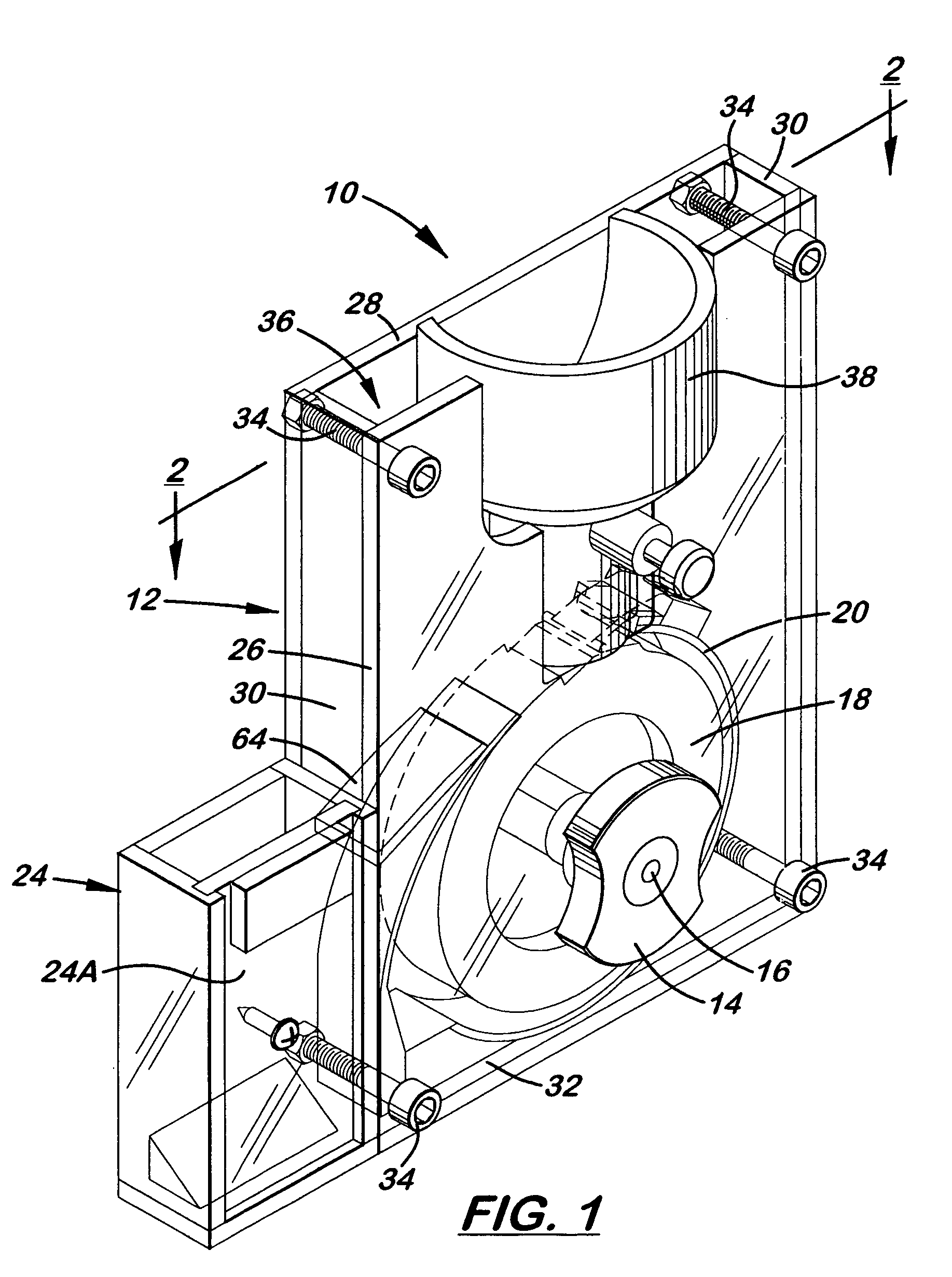
[0017]Referring to the drawings, and particularly to FIGS. 1 to 5, there is illustrated a ball bearing actuation mechanism of the present invention, generally designated 10, for a vending machine (not shown). The ball bearing actuation mechanism 10 basically includes a housing 12, a handle 14 with an elongated shaft 16, a gauge wheel 18, a curved retaining wall 20, a one-way ratchet 22 and an overflow collection receptacle 24.

[0018]The housing 12 of the actuation mechanism 10 has upright front and rear walls 26, 28, upright opposite side walls 30 extending between the front and rear walls 26, 28 and a horizontal bottom wall 32 extending between the front, rear and side walls 26, 28, 30. A plurality of fasteners 34 extend between the front and rear walls 26, 28 of the housing 12 adjacent to its respective corners so as to secure the walls 26–32 together such that the housing 12 forms an interior chamber 36.

[0019]A hopper 38 is supported by the housing 12 between upper portions of the...


PUM


Abstract

A ball bearing actuation mechanism includes a circular gauge wheel rotatably mounted in an interior chamber of a housing below an inlet passage and adjacent to outlet and overflow discharge openings of the housing and a curved retainer wall mounted to the housing in the interior chamber adjacent to a peripheral groove on the gauge wheel so as to form a channel therebetween which extends between the inlet passage and discharge outlet opening of the housing. The peripheral groove has a length preset to receive a preset number of ball bearings in single file fashion therein when the ball bearings are deposited into interior chamber via the inlet passage such that any ball bearings above the preset number deposited into the inlet passage of the housing will divert to the overflow discharge outlet of the housing.

Description

[0001]This patent application claims the benefit of U.S. provisional application No. 60 / 463,253, filed Apr. 16, 2003.TECHNICAL FIELD[0002]The present invention generally relates to vending machines and, more particularly, is concerned with a ball bearing actuation mechanism for a vending machine or the like.BACKGROUND ART[0003]Gaming machines, such as slot machines, in casinos in Japan require the utilization of ball bearings for their operation. Thus players of such machines carry around a bag or container of ball bearings, instead of coins, for insertion into the various gaming machines.[0004]As a consequence of the use of ball bearings by the gaming machines, vending machines in the casinos which are accessed by these players to buy products, such as lollipops and other items, for use while they are operating the gaming machines must likewise utilize ball bearings, instead of coins, for making these purchases. For making purchases of different products, different numbers of ball ...

Claims


Application Information

Patent Timeline
IPC IPC(8): G06F7/08A63F7/02G07F5/04G07F11/00G07F11/44
CPCG07F11/44G07F5/04
Inventor CHANG, KIL JAE
Owner CHANG KIL JAE
Learn More