
Pallet truck tiller arm with angle detector for speed select

a technology of speed select and tiller arm, which is applied in the direction of hand carts, lifting devices, transportation and packaging, etc., can solve the problems of prior art devices, difficult steering of vehicles, and narrow lanes of pallet trucks

Inactive Publication Date: 2006-04-11
RAYMOND LTD
View PDF23 Cites 48 Cited by
  • Summary
  • Abstract
  • Description
  • Claims
  • Application Information

AI Technical Summary

Benefits of technology

The present invention provides a material handling vehicle with a steering mechanism that can selectively change the direction of motion. The steering mechanism can be rotated between a vertical and horizontal position, and an angular position indicator is activated to indicate the angle of rotation. A controller receives the indicator and selects one of several driving states based on the angle of rotation, including a top brake mode, slow speed mode, fast mode, and bottom brake mode. The driving states are progressive, and the controller monitors the changes to ensure valid transitions and activates the brakes if necessary. The invention also provides a pallet truck with a steering mechanism that can produce a two bit state code, which is compared to a present driving state code to determine if the transition is sequential and enter an error mode if not. The technical effects of the invention include improved control and efficiency of material handling vehicles, as well as improved safety and reliability.

Problems solved by technology

Limiting operation in this way, however, poses problems for pallet trucks used in narrow lanes and, in an increasingly common mode of operation, inside of trailers and other large containers for moving goods.
In these applications, the horizontal space available for swinging the tiller to the right and left within the operating arc is limited, and it can therefore be difficult to steer the vehicle when the tiller is pulled too far from the vertical position.
While typically providing the appropriate functions, these prior art devices suffer from a number of disadvantages.
Furthermore, as state changes occur irrespective of the position of the other switch, it is difficult to determine when a failure has occurred, or to adequately monitor changes in driving states.

Method used


Image

  • Pallet truck tiller arm with angle detector for speed select
  • Pallet truck tiller arm with angle detector for speed select
  • Pallet truck tiller arm with angle detector for speed select

Examples


Embodiment Construction

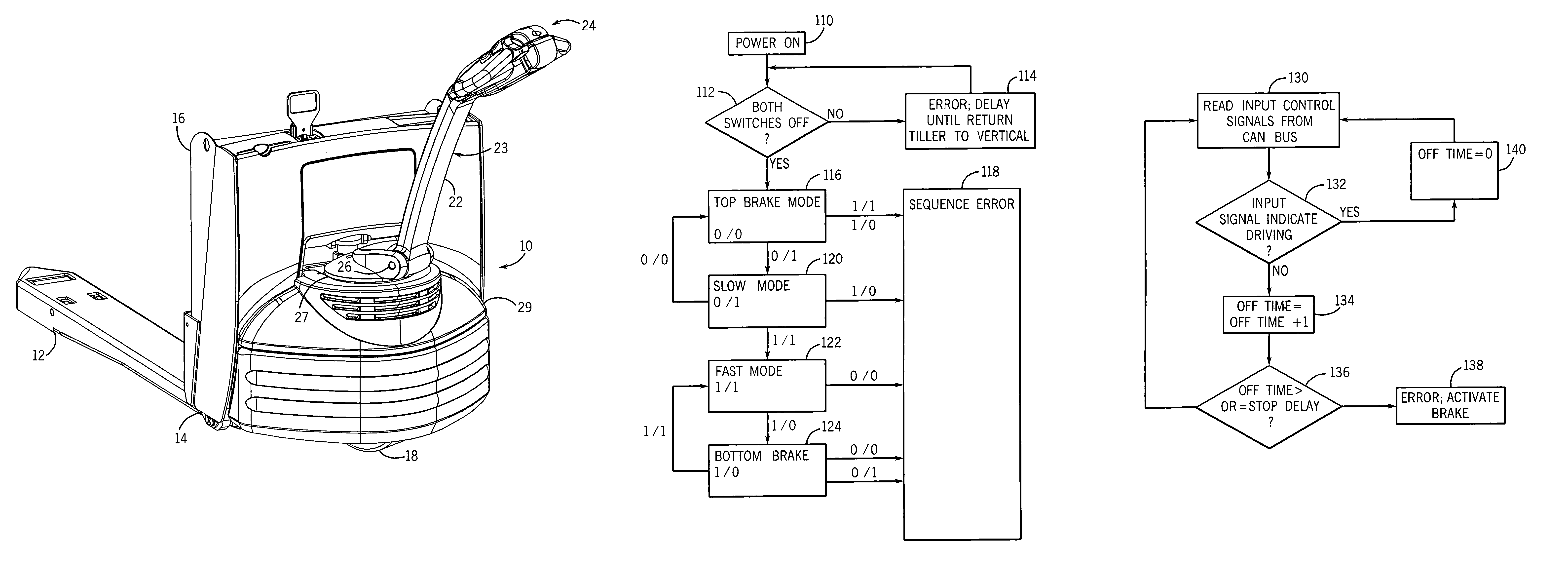
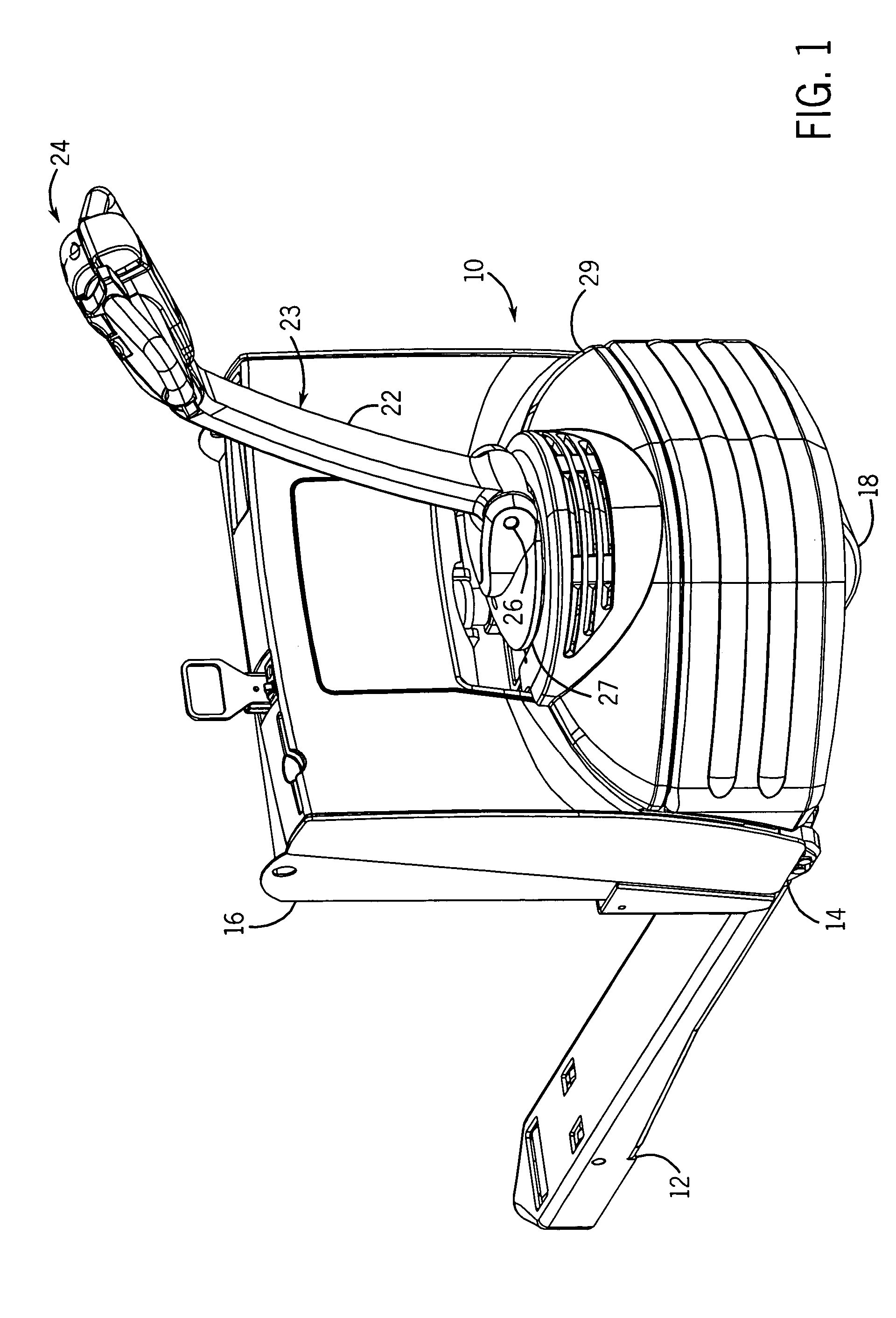
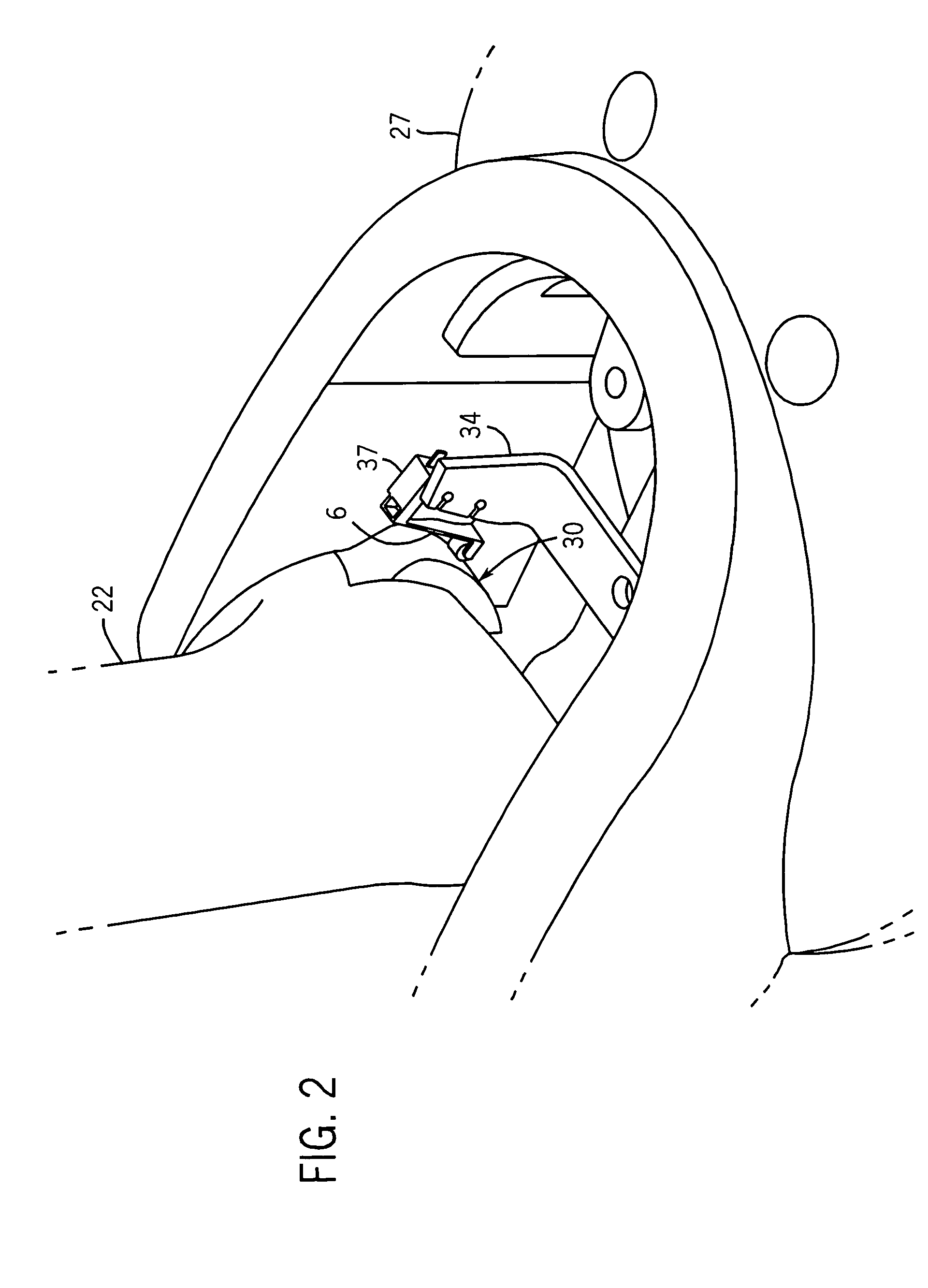
[0022]Referring now to the figures and more particularly to FIG. 1, a pallet truck 10 constructed in accordance with the present invention is shown. The pallet truck 10 comprises forwardly extending forks 12, a drive motor (FIG. 9) provided in a motor compartment 14, a battery (FIG. 9) provided in battery compartment 16, and a steered wheel 18. The steered wheel 18 is coupled to a steering mechanism 23 which includes both a tiller arm 22 and an operator control handle 24. The steering mechanism 23 is rotatable to the right and left to change the direction of the pallet truck 10 and is further movable in an arc between a substantially vertical position and a substantially horizontal position. When in either of the substantially horizontal position or the substantially vertical positions, a deadman brake 84 (FIG. 9) is activated, as described below. To assure that the truck 10 is stopped when the operator leaves the vehicle, the steering mechanism 23 is spring loaded such that it is f...


PUM


Abstract

A motorized pallet truck includes an angular indicator on the steering arm mechanism providing an internal controller with an angular position of the steering arm or tiller. The controller applies a brake when the tiller is in either of a substantially vertical or substantially horizontal position, limits the speed of the truck for a predetermined rotational movement from the vertical position, and allows full speed of the vehicle when the tiller arm is pulled into a predefined fast driving arc.

Description

FIELD OF THE INVENTION[0001]The present invention relates to material handling vehicles and, more particularly, to a material handling vehicle which is steered with a steering tongue or tiller arm including an angle detector for limiting the speed of the vehicle based on the angle of the tiller arm.BACKGROUND OF THE INVENTION[0002]Industrial material handling vehicles such as fork lift trucks or motorized hand pallet trucks are commonly found in warehouses, factories, shipping yards, and, generally, wherever pallets, packages, or loads of goods are required to be moved from place to place. Pallet trucks typically include a load bearing fork or lift arm for lifting packages or pallets to a height sufficient for transporting, an electric drive motor for driving the vehicles, a steering control mechanism, and a brake. These vehicles can include an operator station, on which the operator stands as the pallet truck moves, or can be designed for the operator to walk behind the vehicle at ...

Claims


Application Information

Patent Timeline
Patent Type & Authority Patents(United States)
IPC IPC(8): B62D51/04B62B3/06B62B5/04B62B5/06
CPCB62B3/0612B62D51/04B62B5/063B62B5/0404B62D51/001B66F9/075
Inventor LINDSAY, RYAN PHILIPDAU, VERLE W.BARTELS, ALAN W.
Owner RAYMOND LTD
Learn More