
Apparatus for, and method of, landing items at a well location

a technology for landing items and wells, which is applied in the direction of drilling pipes, wellbore/well accessories, sealing/packing, etc., can solve the problems of unusually heavy casing strings, and inability to reach the location of wells

Inactive Publication Date: 2006-04-11
IRONGATE RENTAL SERVICES LLC
View PDF22 Cites 24 Cited by
  • Summary
  • Abstract
  • Description
  • Claims
  • Application Information

AI Technical Summary

Benefits of technology

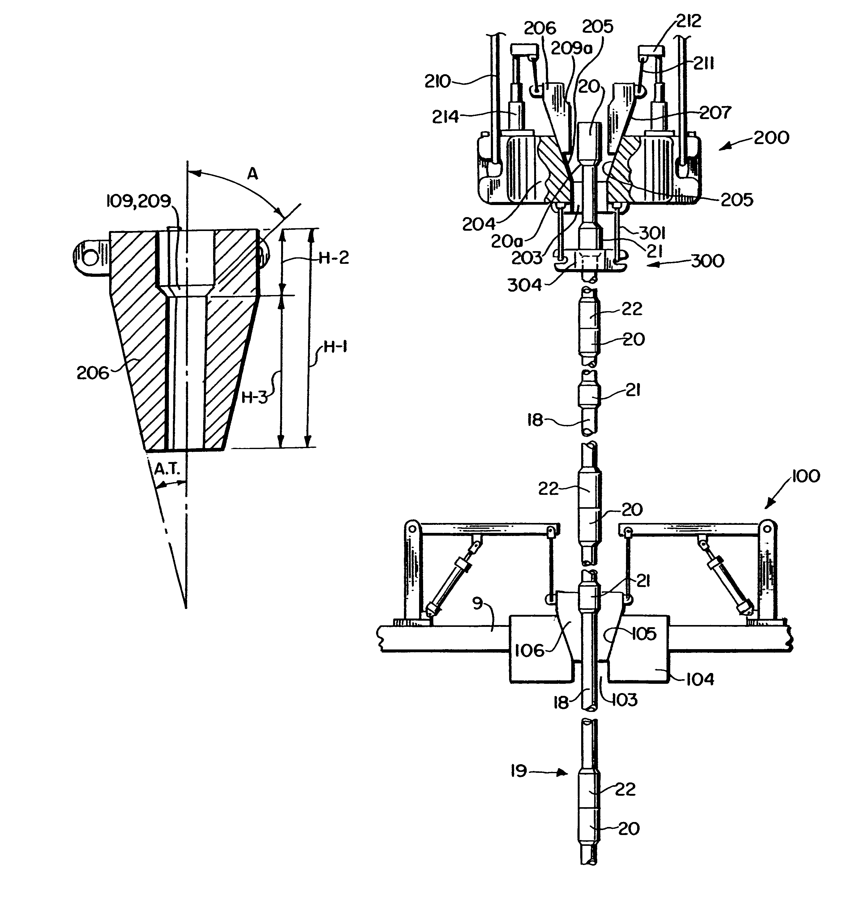
[0025]The present invention does away with the use of prior art slips and provides for the use of upper and lower holders which support the drill pipe without crushing, deforming, scoring or causing elongation of the drill pipe being held. The present invention includes the use of wedge members which can be raised out of and lowered into the holders.
[0027]The enlarged diameter section has a shoulder which corresponds to a shoulder on the movable wedge members of the holders. The engagement of such shoulders provides support for the drill pipe being held without any of the problems associated with the prior art slips, regardless of the weight of the landing string and casing string.

Problems solved by technology

As the world's supply of easy-to-reach oil and gas formations is being depleted, a significant amount of oil and gas exploration has shifted to more challenging and difficult-to-reach locations such as deep-water drilling sites located in thousands of feet of water.
For many reasons, including the nature of the geological formations in which unusually deep drilling takes place and is expected to take place in the future, the casing strings required for such wells must be unusually long and must have unusually thick walls, which means that such casing strings are unusually heavy and can be expected in the future to be even heavier.
Moreover, the landing string needed to land the casing strings in such extremely deep wells must be unusually long and strong, hence unusually heavy in comparison to landing strings required in more typical wells.
In contrast, prior art slips cannot effectively and consistently support the combined landing string and casing string weight of 950,000 to 2,300,000 pounds associated with extremely deep wells, because of numerous problems which occur at such extremely heavy weights.
For example, prior art slips used to support combined landing string and casing string weight above the range of about 610,500 to 1,270,000 pounds have been known to apply such tremendous gripping force that (a) the gripped pipe has been crushed or otherwise deformed and thereby rendered defective, (b) the gripped pipe has been excessively scored and thereby damaged due to the teeth-like grippers on the inside surface of the prior art slips being pressed too deeply into the gripped drill pipe and / or (c) the prior art slips have experienced damage rendering them inoperable.
A related problem involves the uneven distribution of force applied by the prior art slips to the gripped pipe joint.
Such concentration of gripping force in such a relatively small portion of the inner wall of the slips can (a) crush or otherwise deform the gripped drill pipe, (b) result in excessive and harmful strain or elongation of the drill pipe below the point where it is gripped and (c) cause damage to the slips rendering them inoperable.
This uneven distribution of gripping force is not an uncommon problem, as the rough and tumble nature of oil and gas well drilling operations cause the slips and / or master bushing to be knocked about, resulting in misalignment and / or irregularities in the tapered interface between the slips and the master bushing.
This problem is exacerbated as the weight supported by the slips is increased, which is the case for extremely deep wells as discussed above.

Method used


Image

  • Apparatus for, and method of, landing items at a well location
  • Apparatus for, and method of, landing items at a well location
  • Apparatus for, and method of, landing items at a well location

Examples


Embodiment Construction

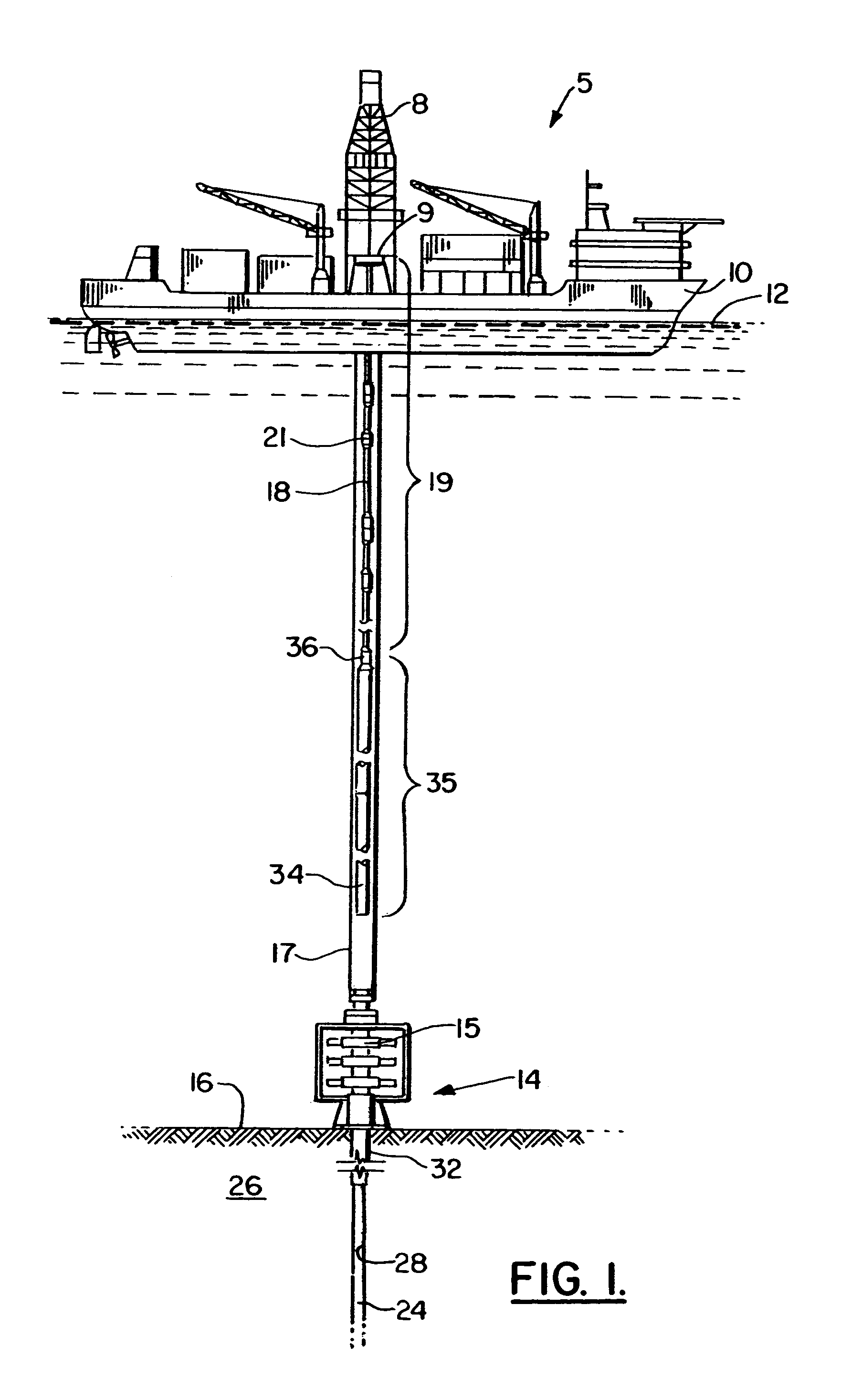
[0068]FIG. 1 depicts generally the present invention 5 in overview. As shown in FIG. 1, drill ship 10 has drilling rig 8 that is situated above ocean surface 12 over the location of undersea well 14 that is drilled below sea floor 16. Numerous lengths or “joints” of drill pipe 18 in accordance with the present invention, attached end-to-end and collectively known as “landing string”19, extend from rig 8. Numerous lengths or “joints” of casing 34, attached end-to-end and collectively known as “casing string”35, extend below landing string 19 and are attached to landing string 19 via crossover connection 36. The landing string 19, crossover connection 36 and casing string 35 are situated longitudinally within riser 17 which extends from the rig 8 to undersea well 14.

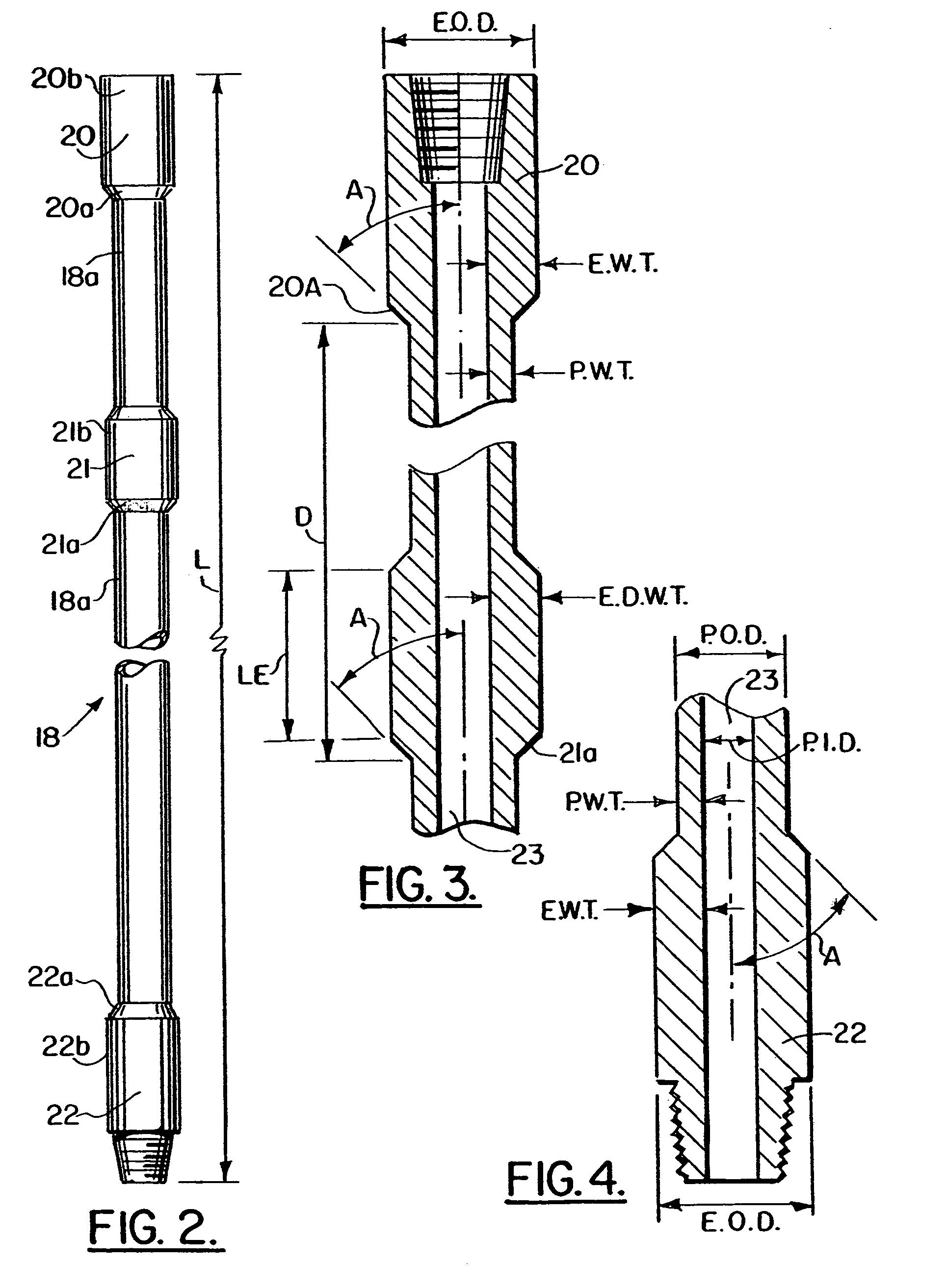
[0069]FIG. 2 shows a drill pipe 18 in accordance with the present invention. In addition to a female or “box” end 20 and a male or “pin” end 22, drill pipe 18 of the present invention also has an enlarged diameter section ...


PUM


Abstract

An apparatus for, and method of, lowering items from a drilling rig to a well located below it. One embodiment includes the use of a landing string comprised of drill pipe having an enlarged diameter section with a shoulder along with upper and lower holders having wedge members also with shoulders that engage and support the drill pipe at the shoulder of the enlarged diameter section. In this embodiment the drill pipe and wedge members can be rotatable with respect to each other.

Description

CROSS-REFERENCE TO RELATED APPLICATIONS[0001]This is a continuation-in-part of U.S. patent application Ser. No. 10 / 055,005, filed Jan. 23, 2002 now U.S. Pat. No. 6,644,413, which in turn was a continuation-in-part of U.S. patent application Ser. No. 09 / 586,239, filed 2 Jun. 2000, (now U.S. Pat. No. 6,378,614 B1), all of which are incorporated herein by reference.[0002]The present application pertains to subject matter which is related to two other patents, namely U.S. Pat. No. 6,349,764 B1, issued Feb. 26, 2002 and entitled “Drilling Rig, Pipe and Support Apparatus” and U.S. Pat. No. 6,364,012 B1, issued Apr. 2, 2002 and entitled “Drill Pipe Handling Apparatus”, each hereby incorporated herein by reference.STATEMENT REGARDING FEDERALLY SPONSORED RESEARCH OR DEVELOPMENT[0003]Not applicableREFERENCE TO A “MICROFICHE APPENDIX”[0004]Not applicableBACKGROUND OF THE INVENTION[0005]1. Field of the Invention[0006]The present invention relates to an apparatus for, and method of, lowering ite...

Claims


Application Information

Patent Timeline
IPC IPC(8): E21B19/06E21B19/07E21B19/16E21B19/18E21B33/035E21B19/00E21B19/10E21B33/043
CPCE21B19/002E21B19/07E21B33/043E21B19/16E21B33/035E21B19/10
Inventor ADAMS, BURT A.SCHAFER, WILLIAM C.HENRY, NORMAN A.
Owner IRONGATE RENTAL SERVICES LLC
Learn More