
Wide lock range phase locked loop and method of operation

a phase lock and wide lock technology, applied in the field of wide lock range phase lock loop (pll) type frequency synthesizers, can solve the problems of increasing power consumption and increasing lockup time, and achieve the effect of enhancing the precision of phase/frequency comparators without decreasing lockup tim

Active Publication Date: 2006-04-04
RENESAS ELECTRONICS CORP
View PDF10 Cites 18 Cited by
  • Summary
  • Abstract
  • Description
  • Claims
  • Application Information

AI Technical Summary

Benefits of technology

[0008]It is an object of the present invention to provide a wide lock range PLL type frequency synthesizer capable of enhancing the precision of a phase / frequency comparator without decreasing the lockup time.
[0009]Another object is to provide a wide lock range PLL type frequency synthesizer capable of suppressing power consumption.

Problems solved by technology

As a result, the switching from a phase unlocked state to a phase locked state is delayed which increases the lockup time.
Also, in the above-described prior art PLL type frequency synthesizer, since all the voltage controlled oscillators are always operated, the power consumption would be increased.

Method used


Image

  • Wide lock range phase locked loop and method of operation
  • Wide lock range phase locked loop and method of operation
  • Wide lock range phase locked loop and method of operation

Examples


Embodiment Construction

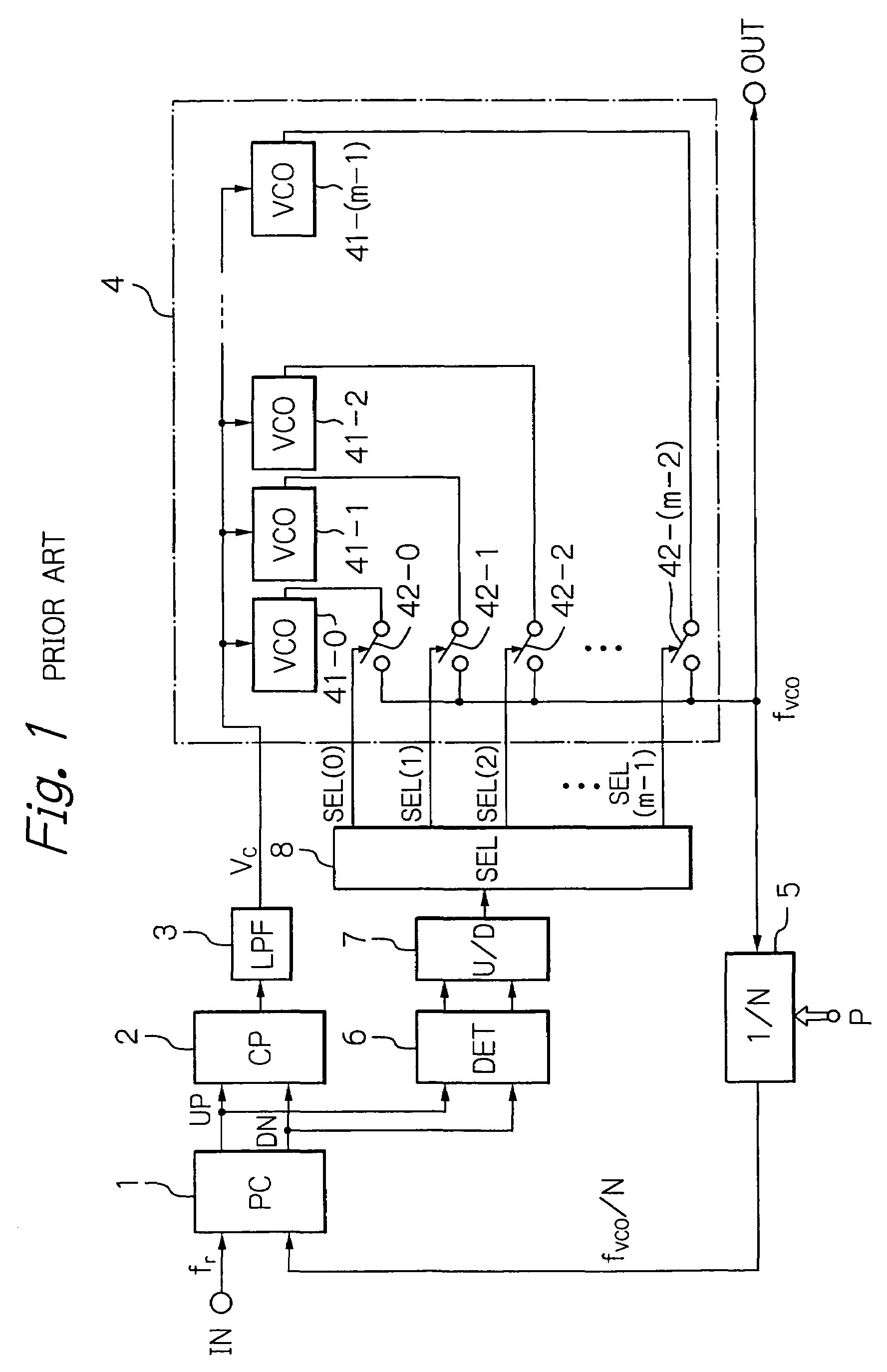
[0020]Before the description of the preferred embodiment, a prior art wide lock range PLL type frequency synthesizer will be explained with reference to FIG. 1 (see: JP-A-10-200406).

[0021]In FIG. 1, the frequency synthesizer receives an input signal IN having a frequency fr to generate an output signal OUT having a frequency of N·fr where N is a variable positive integer supplied from a programmable terminal P.

[0022]A phased-lock loop circuit is constructed by a phase / frequency comparator 1, a charge pump circuit 2, a loop filter 3, a voltage controlled oscillator block 4 and a 1 / N frequency divider 5.

[0023]The phase / frequency comparator 1 compares the phase of the input signal IN with that of an output signal of the 1 / N frequency divider 5 to generate a leading signal UP and a lagging signal DN. As a result, the charge pump circuit 2 charges the loop filter 3 in accordance with the leading signal UP and discharges the loop filter 3 in accordance with the lagging signal DN, so that ...


PUM


Abstract

In a phase locked loop type frequency synthesizer including a phase / frequency comparator for receiving an input signal, a charge pump circuit, a loop filter for generating a control voltage, a voltage control oscillator block including a plurality of voltage controlled oscillators controlled by the control voltage, and a frequency divider formed by a fixed frequency divider and a programmable frequency divider, a selecting circuit selects and activates only one of the voltage controlled oscillators, and counts a number of output pulses of the first frequency divider within a predetermined number of output pulses of the input signal while applying a bias voltage to the loop filter. Thus, the one of the voltage controlled oscillators being selected so that the number of the output pulses of the first frequency divider is brought close to an optimum value.

Description

BACKGROUND OF THE INVENTION[0001]1. Field of the Invention[0002]The present invention relates to a wide lock range phase locked loop (PLL) type frequency synthesizer including a plurality of voltage controlled oscillators and its method for selecting an oscillation frequency.[0003]2. Description of the Related Art[0004]Generally, in a mobile telephone apparatus, a wide lock range PLL type frequency synthesizer having a plurality of voltage controlled oscillators is mounted as a local oscillator to cope with different frequencies.[0005]In a prior art wide lock range PLL type frequency synthesizer (see: JP-A-10-200406) including a PLL circuit having a phase / frequency comparator, a charge pump circuit, a loop filter, a voltage controlled oscillator block formed by a plurality of voltage controlled oscillators and a plurality of switches connected to the voltage controlled oscillators, and a 1 / N frequency divider where N is a positive integer, an unlock control circuit is provided. The ...

Claims


Application Information

Patent Timeline
IPC IPC(8): H03L7/00H03L7/18H03L7/087H03L7/099H03L7/10H03L7/113H03L7/187H03L7/197
CPCH03L7/099H03L7/187H03L7/113H03L7/18
Inventor KAWASUMI, YOKOKUWANO, AKIRAMURATA, YOSHITAKA
Owner RENESAS ELECTRONICS CORP
Learn More