
Quick release sacrificial shield for window assembly

a technology for window assemblies and sacrificial shields, which is applied in the direction of door/window fittings, wing accessories, transportation and packaging, etc., and can solve problems such as the complexity of unauthorised removal of retainers

Inactive Publication Date: 2006-04-04
RICON
View PDF189 Cites 24 Cited by
  • Summary
  • Abstract
  • Description
  • Claims
  • Application Information

AI Technical Summary

Benefits of technology

Simplifies the installation and removal of protective panels, enhances protection for both sides of the glazing, and reduces maintenance costs by preventing damage to the mounting assembly and allowing for quick replacement of panels.

Problems solved by technology

The assembly also includes a retainer that is positioned on the retaining surface such that the retainer retains the piece of glazing within the opening and wherein the retainer is adapted so that when the retainer is positioned on the retaining surface and the first protective panel and the piece of glazing are positioned within the opening, the first protective panel prevents removal of the retainer from the retaining surface.Hence, in this aspect, unauthorized removal of the retainer is complicated as a result of the first protective sheet inhibiting such removal.

Method used


Image

  • Quick release sacrificial shield for window assembly
  • Quick release sacrificial shield for window assembly
  • Quick release sacrificial shield for window assembly

Examples


Embodiment Construction

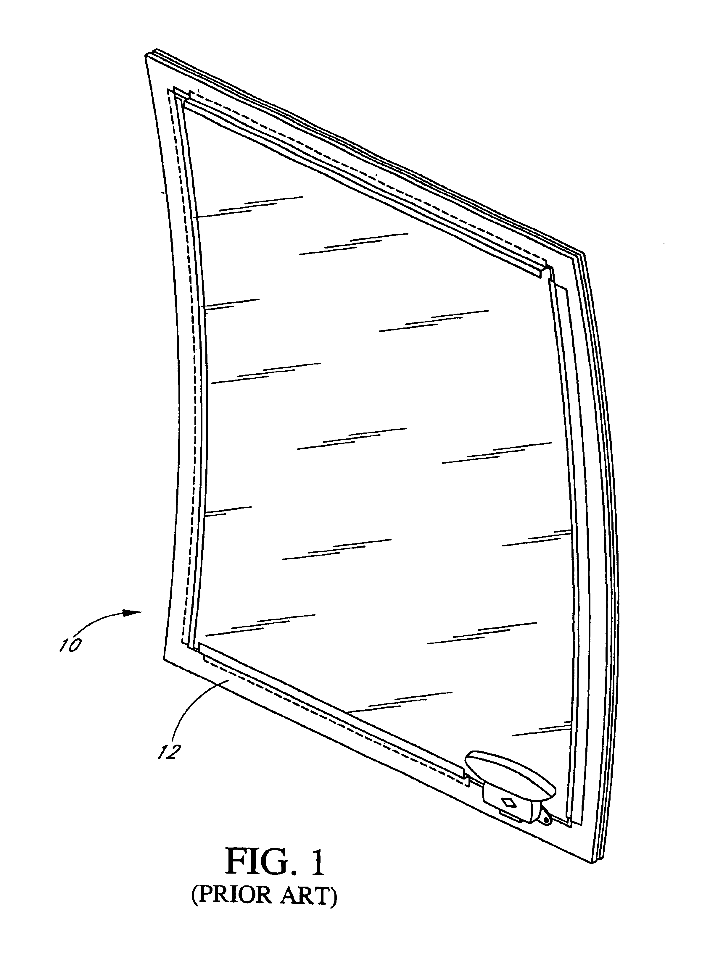
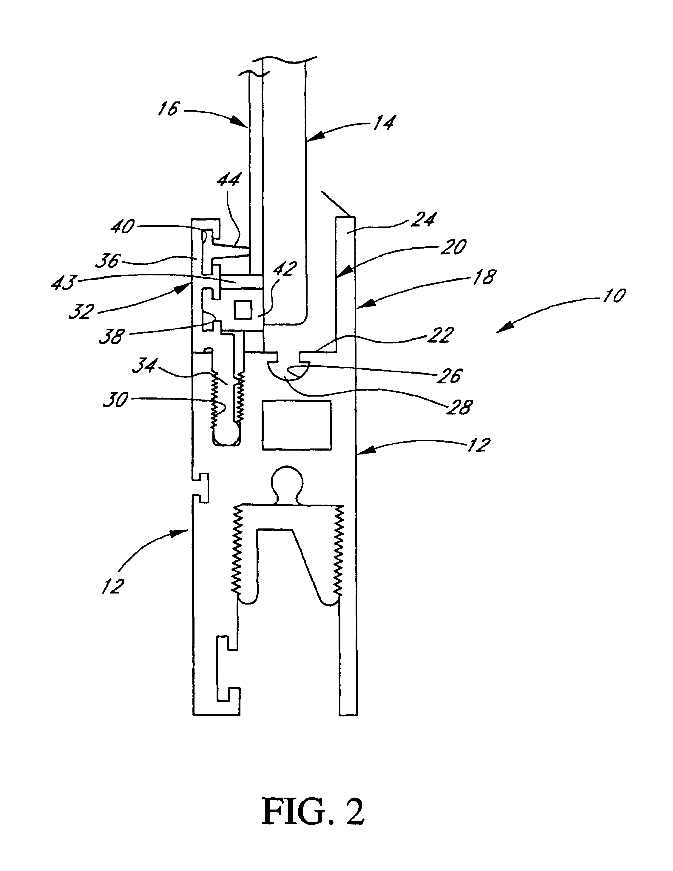
[0018]FIG. 1 depicts a conventional window assembly 10 typically used in mass transit vehicles such as buses and / or trains. With initial reference to FIGS. 1-3, disclosed is one embodiment of a window assembly 10 constructed in accordance with the present invention. The window assembly 10 typically comprises a rectangular or regularly shaped closed frame 12, preferably comprised of metal or rigid plastic, which is mounted to the vehicle (not shown) or, alternatively, could be formed integrally with the vehicle. The frame 12 desirably comprises an inwardly-facing L-shaped support leg 18, which desirably extends about the entire periphery of the frame 12. In the disclosed embodiment, the support leg 18 comprises a transverse base 22 and an inwardly extending support face 24, substantially normal to the base 22, for receiving and supporting a corresponding L-shaped gasket 20. Preferably, the base 22 includes an elongated channel 26 for receiving a corresponding extension 28 from the ga...


PUM


Abstract

Disclosed is a window assembly for use in mass transit vehicles which allows the quick and easy removal and replacement of transparent sacrificial glazing panels which protect the glazing of the window from vandalism and wear. The window assembly utilizes a sacrificial protective panel and mounting arrangement which allows quick and easy replacement of protective panels on one or both sides of the window assembly, but inhibits removal by non-maintenance personnel such as vandals. The frame of the window assembly incorporates one or more retainers which fit into slots along the interior sides of the window frame and sandwich the glazing between the frame and the retainers. In turn, the retainers are essentially “locked” into position in the frame by an inner protective panel, which significantly inhibits the removal of the retainers from the window assembly when the protective panel is in its desired position against the windowpane. Once the inner protective panel is removed from the window assembly, however, the retainers and glazing can quickly and easily be removed from the frame, allowing the glazing and any remaining protective panels to be quickly and easily removed from the frame.

Description

RELATED APPLICATIONS[0001]The present application is a continuation of U.S. patent application Ser. No. 10 / 057,617 filed Jan. 23, 2002, entitled Quick Release Sacrificial Shield For Window Assembly now U.S. Pat. No. 6,688,044, issued Feb. 10, 2004, which was a continuation of U.S. patent application Ser. No. 09 / 395,692 filed Sep. 13, 1999, entitled Quick Release Sacrificial Shield For Window Assembly now U.S. Pat. No. 6,408,574, issued Jun. 25, 2002 which was a continuation-in-part of U.S. patent application Ser. No. 09 / 186,513, filed Nov. 4, 1998, entitled Quick Release Sacrificial Shield For Window Assembly now U.S. Pat. No. 6,205,723, issued Mar. 27, 2001.FIELD OF THE INVENTION[0002]The present invention relates to window assemblies and apparatus for protecting the glazing of motor vehicles. More particularly, the present invention relates to a window assembly for use in mass transit vehicles which allows the quick and easy removal and replacement of transparent sacrificial prote...

Claims


Application Information

Patent Timeline
Patent Type & Authority Patents(United States)
IPC IPC(8): E05F11/38E06B3/00E06B7/16B60J1/00B60JB60J1/10B60J1/16B60J1/20B60J11/00B61D25/00E06B3/26
CPCB60J1/2094
Inventor FARRAR, JERRY L.SHEPARD, JESSE E.
Owner RICON
Learn More