
Temperature control

a technology of temperature control and slave zone, applied in computer control, temperatue control, special data processing applications, etc., can solve problems such as loss of temperature measurement information, deviation of temperature of slave zone(s) from desired temperature, and failure of communication between sensors, so as to improve temperature control

Active Publication Date: 2006-03-28
D M E CO
View PDF12 Cites 24 Cited by
  • Summary
  • Abstract
  • Description
  • Claims
  • Application Information

AI Technical Summary

Benefits of technology

"The present invention provides a method and apparatus for controlling temperature in a plant with multiple temperature control zones. The invention allows for improved temperature control by controlling devices in one zone based on an effective control parameter for another zone. Additionally, the invention compensates for differences in temperature control characteristics between the zones by using an offset value that includes a fixed and variable component. This results in more precise and accurate temperature control in each zone."

Problems solved by technology

Loss of temperature measurement information may arise from failure of a sensor, failure of communication between the sensor and control, or failure of control components that process sensor signals to generate measured temperature information for subsequent control processing.
It is known that because of differences in temperature control characteristics between slave zones and the master zone, use of the effective control parameter of the master zone can result in the temperature of the slave zone(s) deviating from the desired temperature.
While such deviations are of no consequence in some controlled plants, they may have adverse consequences in others.
A hot runner system for injection molding is an example of a controlled plant in which such deviations may have adverse consequences, potentially resulting in production of articles of unacceptable quality.

Method used


Image

  • Temperature control
  • Temperature control
  • Temperature control

Examples


Embodiment Construction

[0017]The invention shall be illustrated with reference to preferred embodiments which shall be described in detail. The illustration and description of the preferred embodiments is intended only to provide information to assist in understanding of the invention. In the following description and in the appended claims, the terms “master temperature control zone” and “master zone” shall be used interchangeably with the terms “first temperature control zone” and “first zone”; and, the terms “slave temperature control zone” and “slave zone” shall be used interchangeably with “second temperature control zone” and “second zone”.

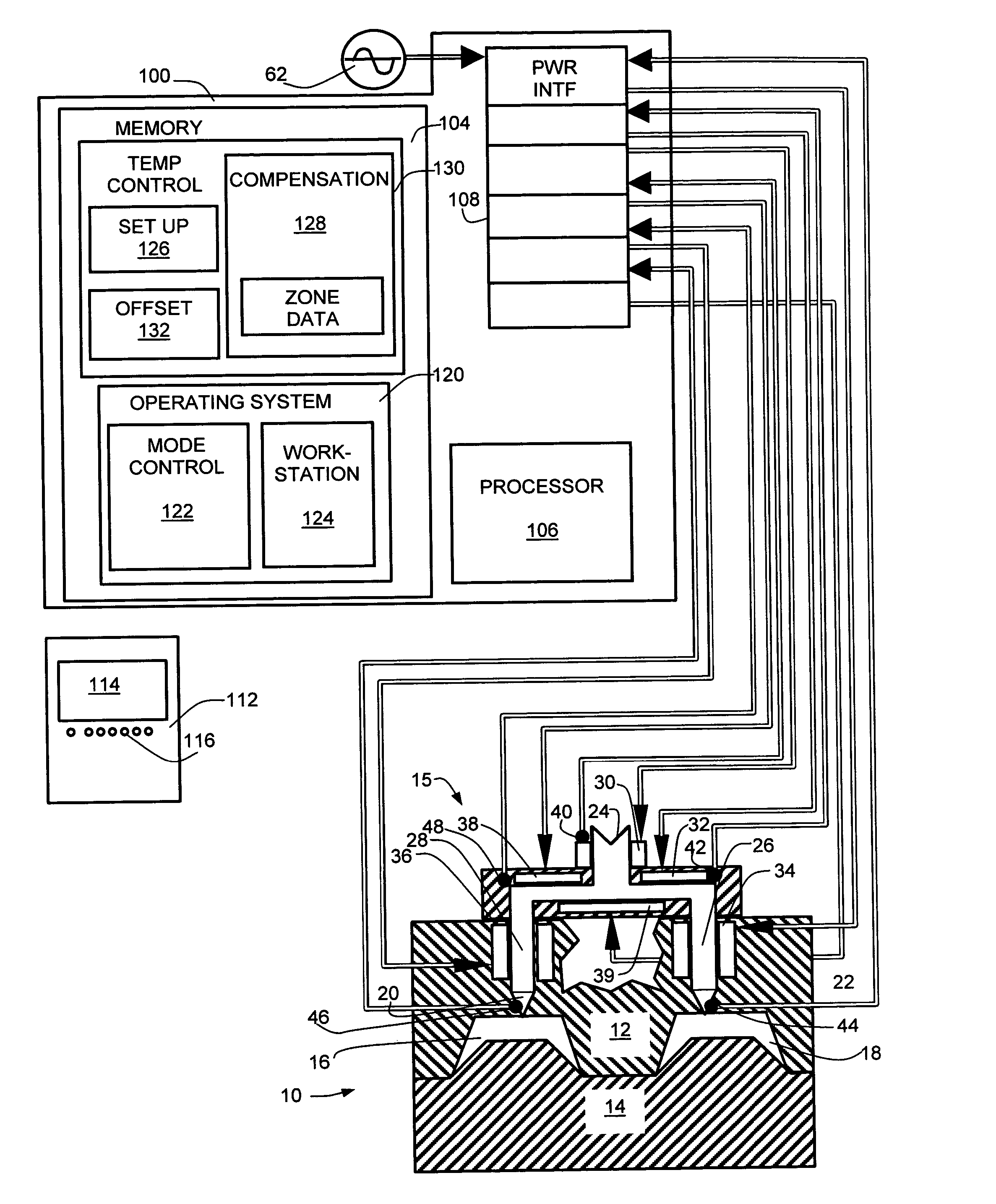
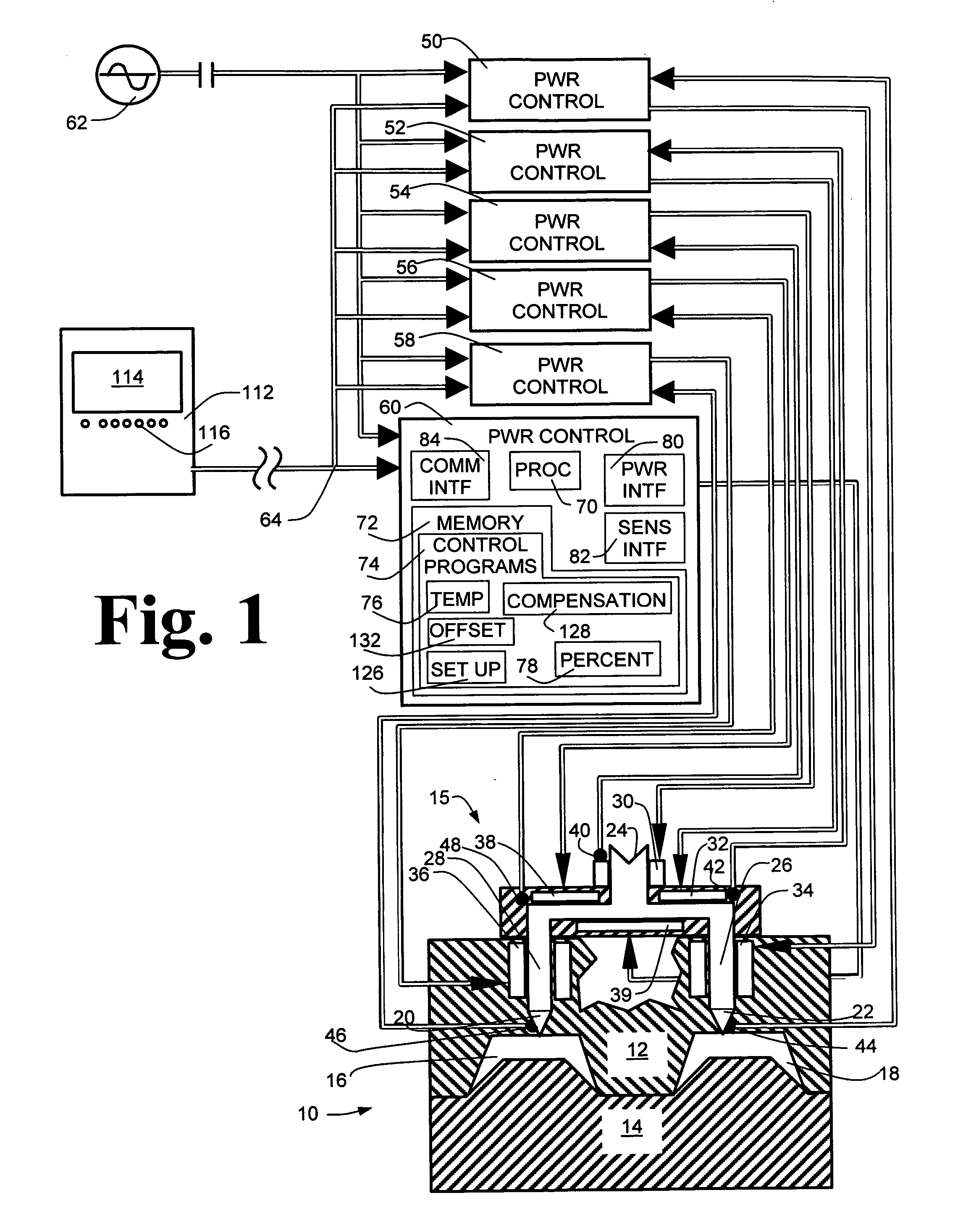
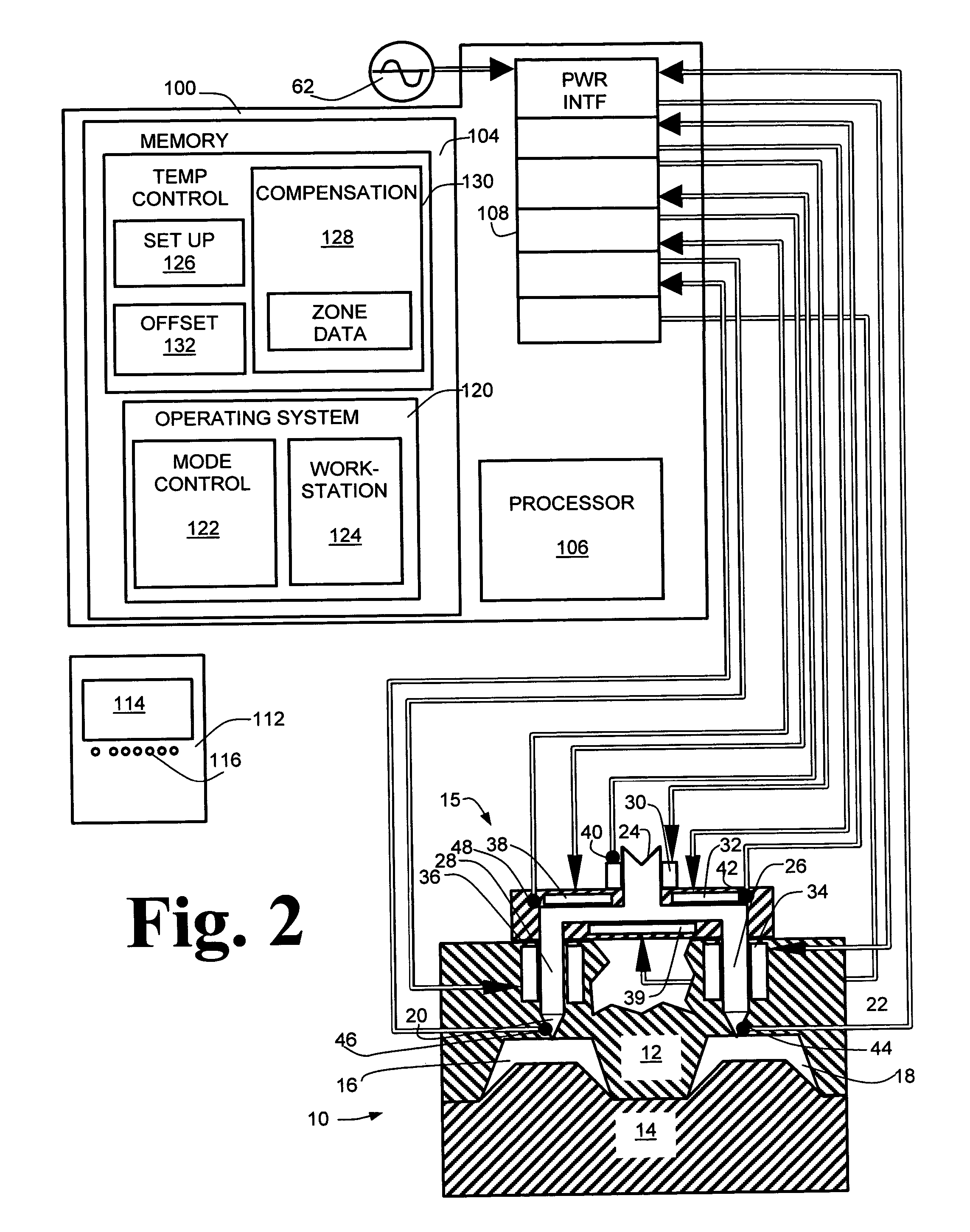
[0018]Referring to FIG. 1, a mold assembly 10 comprises mold halves 12 and 14 defining mold cavities 16 and 18 along the parting line of the mold halves. Mold halves 12 and 14 are shown in cross-section and mold half 12 is shown with a partial cut-away. Cavities 16 and 18 determine the shape, size and finish of articles to be molded using mold assembly 10. Molding...


PUM

PropertyMeasurementUnit
temperatureaaaaaaaaaa
heating capacityaaaaaaaaaa
resistanceaaaaaaaaaa

Abstract

A method and apparatus are disclosed for controlling temperature of a plant comprising plural temperature control zones, wherein an effective control parameter for a first zone for which a signal representing measured temperature is available is produced according to an algorithm relating measured temperature, a desired temperature and a control parameter associated with a device affecting temperature in the first temperature control zone, the effective control parameter is summed with an offset value representing a proportional offset of the effective control parameter of a second temperature control zone relative to the effective control parameter of the first temperature control zone and the result is applied to control a device affecting temperature in the second temperature control zone. Advantageously, the offset value comprises a fixed amount and a variable amount, the variable amount accounting for dynamic differences in temperature control characteristics of the first and second temperature control zones.

Description

I. BACKGROUND OF THE INVENTION[0001]1. Field of the Invention[0002]This invention relates generally to temperature control of a plant having plural temperature control zones. In particular, this invention relates to controlling devices affecting temperature in temperature control zones wherein control in one or more selected zones is effected according to the effective control parameter of another zone.[0003]2. Description of Related Art[0004]It is known to arrange controls for devices affecting temperature of controlled plants, whether the controlled plant is equipment or a building, in plural temperature control zones. Each temperature control zone associates at least one device for affecting temperature with a control for controlling operation of the device. The number of zones and the proximity of devices from zone to zone are chosen to achieve an acceptable range of temperature variation within the temperature control zones. For example, in temperature control of injection mold...

Claims


Application Information

Patent Timeline
Patent Type & Authority Patents(United States)
IPC IPC(8): B29C45/00B29C45/73B29C45/78G05D23/19
CPCG05D23/1932Y10T29/49158Y10T29/4916
Inventor LINEHAN, THOMASSCHROEDER, FRED
Owner D M E CO
Learn More